
Watch the complete tutorial
Airborne Relay 3.0 topology comparison
| Topology | Controllers | Aircraft | Control arrangement |
|---|---|---|---|
| Single relay / single controller | 1 | 1 relay + 1 main | One pilot switches between relay and main |
| Single relay / dual controller | 2 | 1 relay + 1 main | Separate relay and main responsibilities |
| Single relay / triple aircraft | 2 | 1 relay + 2 main | Each RC controls a main; Main & Relay RC also controls relay |
| Dual relay / dual controller | 2 | 2 relays + 1 main | Relay RC switches relays; Main RC controls main |
Choose one of four relay topologies
The relay aircraft supports the communication path while the main aircraft performs the task. DJI demonstrates four combinations of controllers and aircraft. The arrangement determines who can control each aircraft and which signal information appears on each controller.
Choose the topology around the crew and the planned signal path. Sketch the controller, relay and main-aircraft positions before setup, and label each physical aircraft so its on-screen role is easy to confirm.
- Single-Relay, Single-Controller: one controller, one relay and one main aircraft.
- Single-Relay, Dual-Controller: two controllers, one relay and one main aircraft.
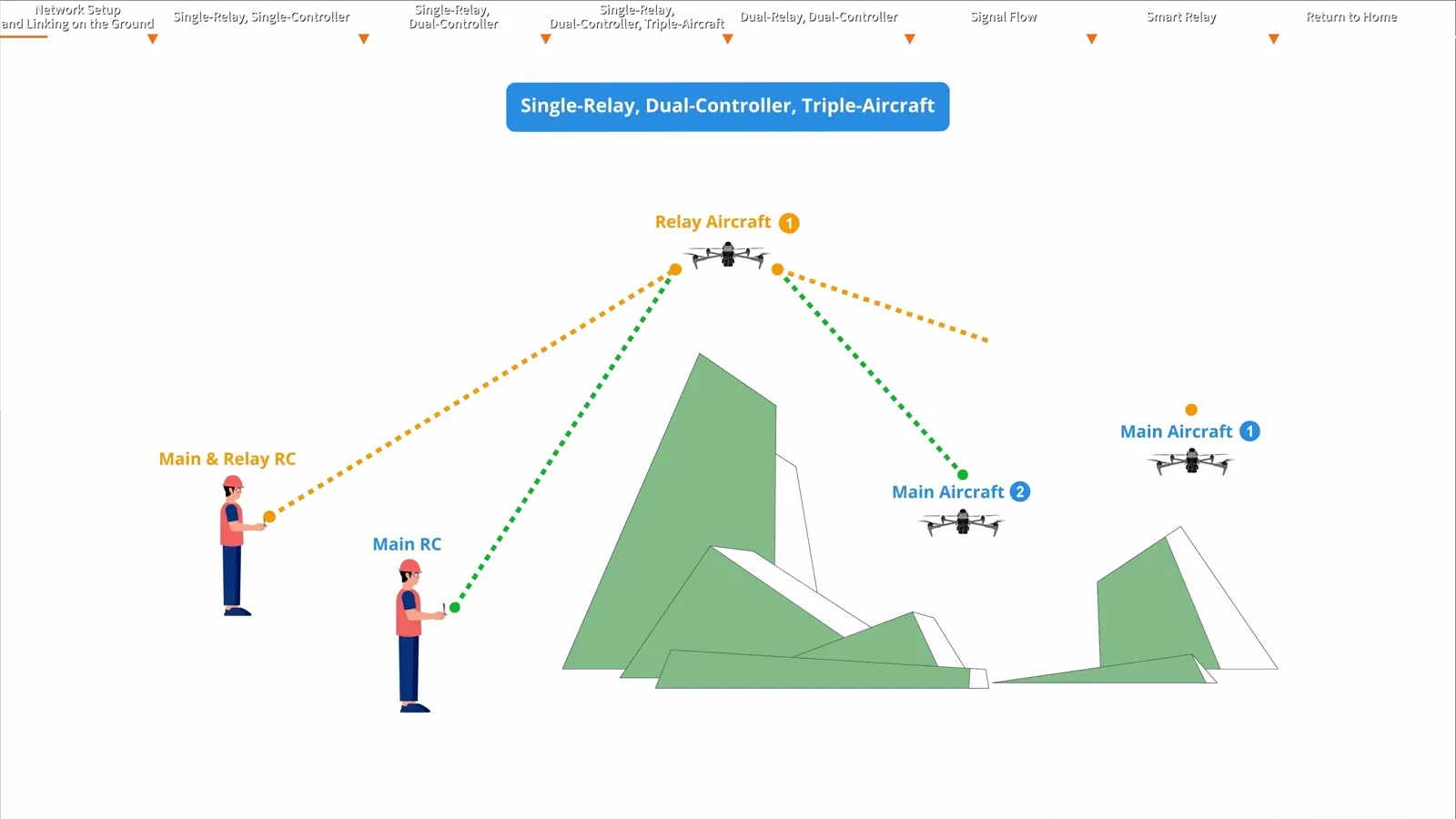
- Single-Relay, Dual-Controller, Triple-Aircraft: two controllers, one relay and two main aircraft.
- Dual-Relay, Dual-Controller: two controllers, two relays and one main aircraft.
Open Relay Network Setup and identify controller roles
Power on the devices and place them together near the controller. The tutorial builds the triple-aircraft arrangement and explains that the other topologies use the same setup process with different device counts.
A Main RC controls only its main aircraft. A Relay RC controls the relay aircraft. A Main & Relay RC can switch between its main and relay aircraft. Make these responsibilities explicit before connecting the network.
The most complex arrangements shown contain three aircraft and two controllers: up to five devices are selected together during setup.
- Open Relay Network Setup on the DJI Pilot 2 homepage.
- Select the usage scenario that matches the intended topology.
- Identify the Main RC, Relay RC or Main & Relay RC responsibilities in the selected arrangement.
Put aircraft into findable mode
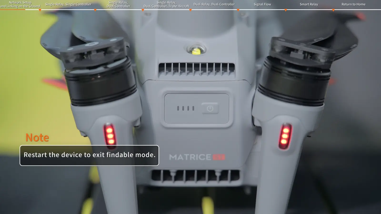
Press each aircraft's power button three times in quick succession. Sequential blinking of the power indicators confirms findable mode. On the device-search page, the controller continuously searches for nearby discoverable devices.
Discovery order initially assigns the roles. That makes the next step important: the first aircraft found is not automatically the aircraft your crew intended for that role.
The on-screen note states that restarting the device exits findable mode. If you restart during preparation, repeat the discovery step before continuing network setup.
A device that is not detected for five seconds is treated as offline and disappears from the device list. Keep the devices powered and together while completing discovery.
- Press each aircraft power button three times quickly.
- Confirm its power indicators blink in sequence.
- Open the device-search page and wait for the aircraft to appear.
Assign and physically verify aircraft roles
Drag the aircraft icons on the controller screen to change their roles. To identify a particular physical aircraft, press its power button once; its app icon flashes brightly for three seconds. Use this check for every aircraft before moving on.
- Drag icons into the intended relay and main roles.
- Press one aircraft's power button once.
- Match it to the icon that flashes for three seconds.
- Repeat until the crew can identify each aircraft and its role.
Join the second controller and finish linking
On the second controller, open Relay Network Setup and join the network. The tutorial uses Join Networking, shows the aircraft icons, and confirms successful setup with Linking Successful. Follow any setup-failure prompt before continuing.
Keep the joining controller on its linking page and continue on the controller that initiated network setup. The joining controller is now discoverable by that network; leaving the page interrupts this setup stage.
- Open Relay Network Setup on the second controller.
- Tap Join Networking and confirm the displayed aircraft.
- Complete the prompted setup and look for Linking Successful.
- To leave the established network, follow the demonstrated five-second aircraft power-button hold to relink, or restart network setup.
Read the signal for the selected topology
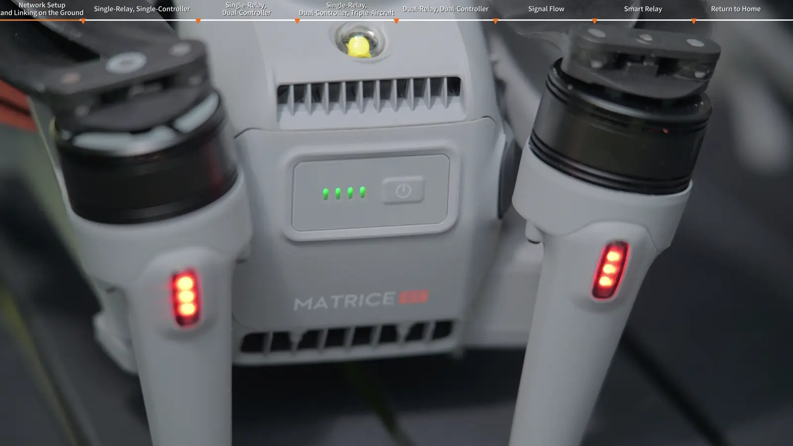
On a Main RC, the video-transmission indicator is the Composite Signal for the aircraft being operated. When controlling a relay, the display exposes the relevant link segments. This lets the pilot distinguish an overall working-aircraft link from the individual sections that support it.
In the single-relay arrangements, the relay view shows controller-to-relay and relay-to-main links. In the triple-aircraft arrangement, each controller operates one main aircraft, and the Main & Relay RC can also switch to the relay.
In the dual-relay arrangement, the Main RC's overall signal is the weakest of the three segments. Relay Aircraft 1 shows Relay RC-to-Relay 1 and Relay 1-to-Relay 2. Relay Aircraft 2 shows Relay 1-to-Relay 2 and Relay 2-to-main. Review the weak segment before changing a relay position.
Switch aircraft and open Relay Split Screen
Tap the main or relay aircraft icon at the bottom of the screen to switch control where the controller role permits it. The camera view and signal display change with that selection. Confirm the selected aircraft before giving an input.
- Tap the intended aircraft icon to switch control.
- Verify the camera view and signal display changed to that aircraft.
- Hold R3 to open Relay Split Screen and view the other aircraft's auxiliary video stream.
Monitor the complete network during the mission
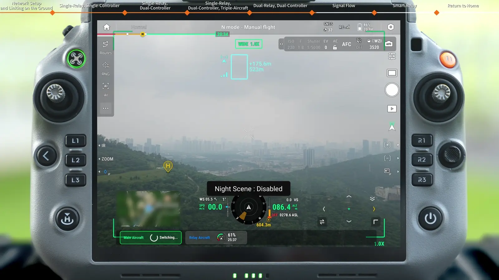
The tutorial shows AR positions when the two aircraft are more than 500 metres apart. HMS information and battery levels appear at the bottom centre, while the map shows aircraft positions and signal quality. These displays answer different questions: where each aircraft is, how it is doing, and how the link is performing.
As the main aircraft moves farther away, adjust the relay position as needed. Keep watching the signal bars and maintain a clear physical path between the controller and relay. Include relay battery state in the same scan as the working aircraft's battery.
Start and supervise Smart Relay
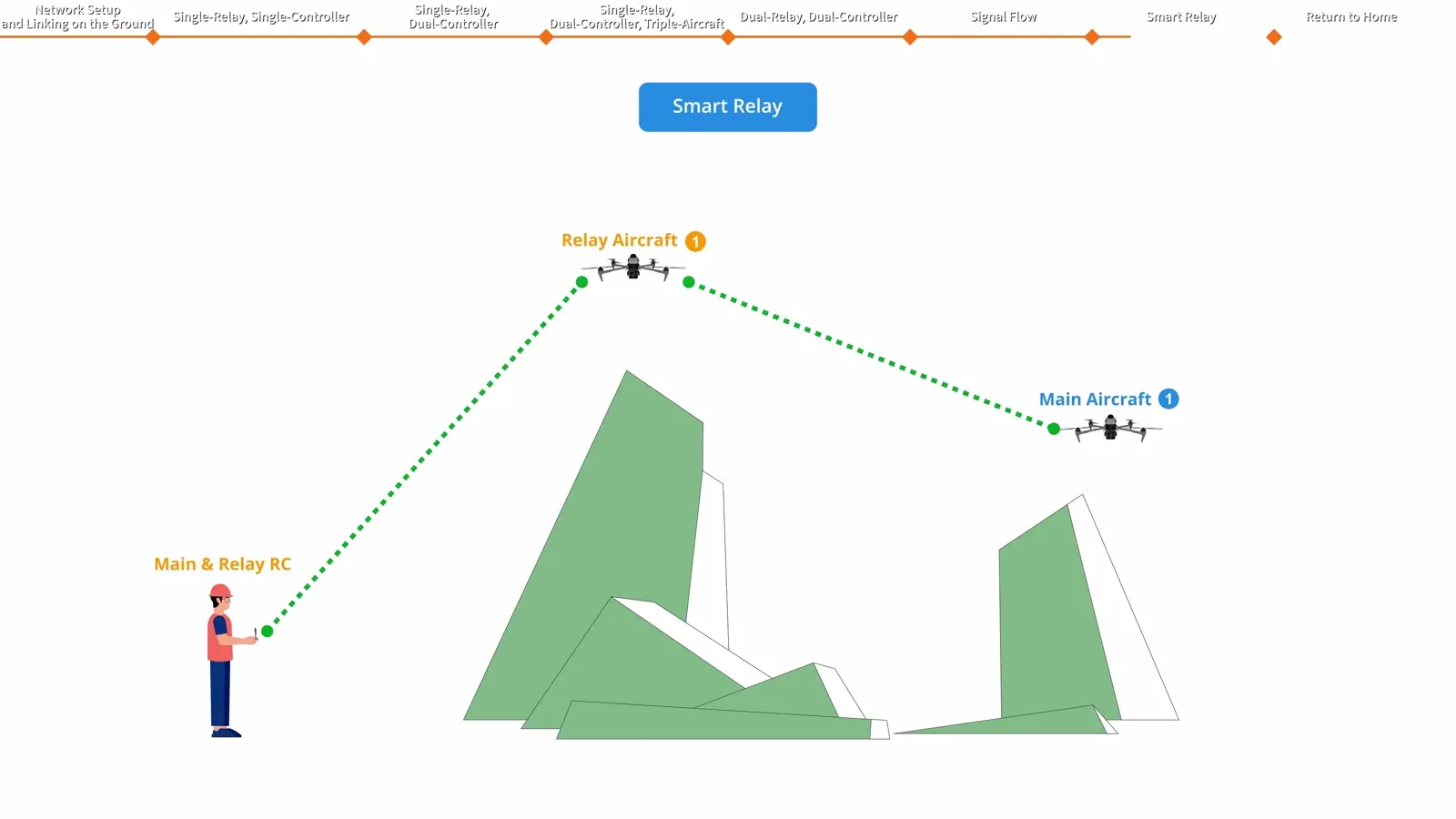
Smart Relay automatically adjusts the relay aircraft's position as the main-aircraft-to-controller distance changes. In the demonstrated sequence, enabling it in relay mode starts automatic relay takeoff; the pilot then switches to main-aircraft mode and takes off.
- Select relay mode and enable Smart Relay.
- Observe the relay aircraft's automatic takeoff.
- Switch to main-aircraft mode and take off.
- Monitor the relay signal bars and take over manually if the signal becomes poor.
Return from farthest to nearest
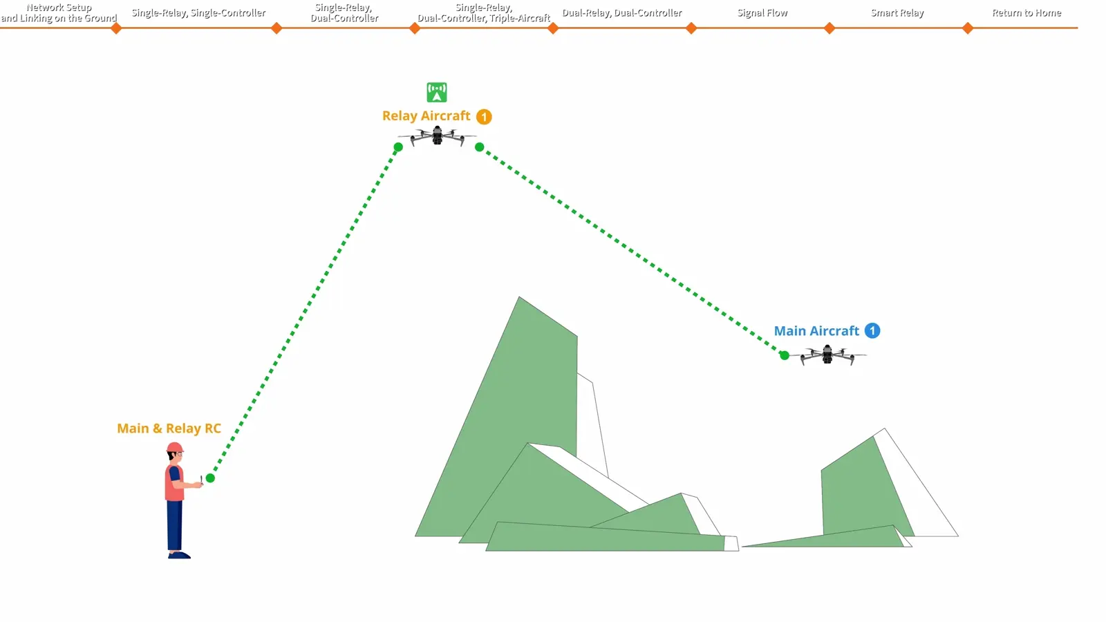
Return the farthest main aircraft first, then recover relay aircraft in sequence. In a dual-relay network, the order is main aircraft, Relay Aircraft 2, then Relay Aircraft 1. This preserves the supporting communication path while the distant aircraft comes back.
In Smart Relay mode, initiating RTH on the main aircraft makes the relay follow it back and hover above the home point. The relay still needs enough battery to support that return. If the relay initiates its own RTH, Smart Relay disables automatically; monitor the main aircraft's signal closely at that point.
- Recover the farthest main aircraft first.
- In dual-relay mode, return Relay 2 before Relay 1.
- Monitor all battery levels throughout the recovery.
- Confirm each aircraft's return and landing before closing the operation.
Your session checklist
Use these points to review the workflow with your crew.
- Topology and controller roles agreed
- Every aircraft identified with the three-second icon flash
- Linking Successful confirmed
- Composite and segment signals understood
- Aircraft selection checked before control inputs
- Relay batteries included in monitoring
- Far-to-near recovery sequence briefed
Questions & answers
How do I put Matrice 5T into relay findable mode?
Press its power button three times in quick succession. The power indicators blink in sequence when findable mode is active.
How do I identify an aircraft during relay setup?
Press that aircraft’s power button once. Its icon in the app flashes brightly for three seconds; use that to verify its assigned role.
What is the return order for two relays?
Return the main aircraft first, then Relay Aircraft 2, then Relay Aircraft 1. The tutorial calls this the far-to-near principle.
What happens if the relay starts RTH during Smart Relay?
Smart Relay disables automatically. Monitor the main aircraft’s signal as the relay returns; plan sufficient relay battery for the complete operation.
Video transcript
Read the complete transcript
Welcome to our tutorial video for DJI Matrice 5T
where we will introduce the multi-aircraft relay feature of the DJI Matrice 5T aircraft
Matrice 5T can serve as a relay aircraft to provide relay service for other Matrice 5T aircraft
This further extends the communication range for emergency searches across mountains and undulating terrain
and in urban areas where buildings block the signal
The following four relay topologies are supported
1.Single-Relay, Single-Controller
1 remote controller + 1 relay aircraft + 1 main aircraft
One pilot uses a single remote controller to switch control between the two aircraft
which is ideal for single-person operations across mountains and obstacles
2.Single-Relay, Dual-Controller
2 remote controllers + 1 relay aircraft + 1 main aircraft
Two pilots divide the work
one focuses on positioning the relay aircraft
while the other focuses on the main aircraft 's tasks
3.Single-Relay, Dual-Controller, Triple-Aircraft:
2 remote controllers + 1 relay aircraft + 2 main aircraft
One relay aircraft serves two main aircraft at the same time
which is ideal for searching for multiple targets simultaneously
4.Dual-Relay, Dual-Controller
2 remote controllers + 2 relay aircraft + 1 main aircraft
Two levels of relay pass the signal along for ultra-long-distance operations or scenarios with multiple obstructions
Make sure all devices are powered on and placed together near the remote controller
On the DJI Pilot 2 homepage
tap "Relay Network Setup" to enter the relay network setup and linking page
Select the usage scenario based on your operational needs
This video demonstrates Single-Relay, Dual-Controller, Triple-Aircraft mode
The setup process is identical for the other topologies
only the number of devices differs
The Main RC controls only the main aircraft
the Relay RC controls only the relay aircraft
and the Main & Relay RC can switch between controlling the main aircraft and the relay aircraft
Press the power button of each aircraft three times in quick succession
When the power indicators blink in sequence
the aircraft has entered findable mode
After entering the device search page
the remote controller continuously searches for nearby devices in findable mode
During scanning
detected devices are automatically assigned roles in the order in which they are found
You can drag the aircraft shown on the remote controller screen to change their roles
Press the power button of an aircraft once
and its icon in the app will blink brightly for 3 seconds
so you can confirm whether it is the relay aircraft or a main aircraft
On the second remote controller
tap "Relay Network Setup" on the DJI Pilot 2 homepage and join the network
Tap "Join Networking"
Once the screen shows the two aircraft icons
you can enter the camera view
If a network setup failure is prompted
follow the prompts to make the corresponding adjustments
Once networked
the App confirms "Linking Successful" and returns to the home screen after 2 seconds
After the network is set up
to exit the network
press and hold each aircraft's power button for 5 seconds to relink or restart network setup
Single-Relay, Single-Controller
When the Main & Relay RC controls the relay aircraft
the relay signal shows the signal from the remote controller to the relay aircraft and from the relay aircraft to the main aircraft
When the Main & Relay RC controls the main aircraft
the video transmission signal is the Composite Signal of the aircraft being operated
Single-Relay, Dual-Controller
On the Main RC
the video transmission signal is displayed as the Composite Signal
On the Relay RC
the signal simultaneously displays the link from the remote controller to the relay aircraft and from the relay aircraft to the main aircraft
Single-Relay, Dual-Controller, Triple-Aircraft
Each of the two remote controllers controls one main aircraft
and the Main & Relay RC can also control the relay aircraft
The Main RC can only control its main aircraft
and its video transmission signal is the Composite Signal of the aircraft being controlled
When the Main & Relay RC controls its main aircraft
the video transmission signal is the Composite Signal of the aircraft being controlled
When the Main & Relay RC controls the relay aircraft
the relay signal shows the signal from the remote controller to the relay aircraft and from the relay aircraft to the main aircraft
Dual-Relay, Dual-Controller
The Relay RC can control either relay aircraft individually
while the Main RC controls only the main aircraft
On the Main RC
the video transmission signal is the Composite Signal
and the overall signal shown is the weakest of the three link segments
When the Relay RC controls Relay Aircraft 1
the video transmission displays the signal from the Relay RC to Relay Aircraft 1
and from Relay Aircraft 1 to Relay Aircraft 2
When the Relay RC controls Relay Aircraft 2
the video transmission displays the signal from Relay Aircraft 1 to Relay Aircraft 2
and from Relay Aircraft 2 to the main aircraft
During operation
tap the main aircraft or relay aircraft icon at the bottom of the screen to switch control
The camera view and signal display switch accordingly
During flight
you can monitor the overall status in the following ways:
Press and hold the R3 button on the remote controller to open Relay Spilt Screen mode
and view the auxiliary video stream of the other aircraft
AR projection:
when the two aircraft are more than 500 meters apart
the relay aircraft and the main aircraft display each other's positions
Status sync:
the HMS information and battery levels of the relay aircraft and the main aircraft are displayed at the bottom center of the screen
The map displays the projected positions and signal quality of the relay aircraft and the main aircraft
As the main aircraft flies farther away
adjust the position of the relay aircraft as needed
Always monitor the signal bars to keep the signal stable
and make sure there are no physical obstructions between the remote controller and the relay aircraft
When Smart Relay is enabled
the relay aircraft automatically adjusts its position as the distance between the main aircraft and the remote controller changes
to maintain the optimal relay link
In relay mode
enable Smart Relay and the relay aircraft will take off automatically
Then switch to main aircraft mode and take off
Keep monitoring the signal bars of the relay aircraft
If the signal becomes poor
take over manually
Follow the far-to-near principle for RTH
return the farthest main aircraft first
and then return the relay aircraft in sequence
In the Dual-Relay, Dual-Controller scenario
after the main aircraft returns
return Relay Aircraft 2 and then Relay Aircraft 1
from far to near
to prevent the link from disconnecting early
Note: In Smart Relay mode
when the main aircraft initiates RTH
the relay aircraft follows it back and hovers above the Home Point
Make sure the relay aircraft has sufficient battery power during operation
If the relay aircraft initiates RTH
Smart Relay will be disabled automatically
In this case
pay extra attention to the signal strength of the main aircraft to avoid losing the signal
Thank you for watching