
2.6.1 Introduction to the visual perception system
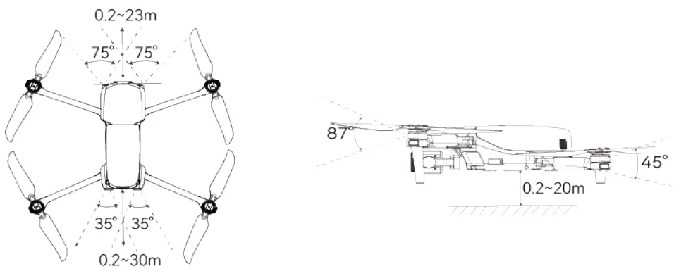
PDF p. 23The aircraft adopts a three-directional visual perception system design to achieve avoidance performance of front, rear, and bottom, ensuring precise positioning and safe flight of the aircraft. PDF p. 23
The visual perception system is a vision-based positioning system that perceives obstacles and obtains aircraft position information through visual image ranging. The aircraft's visual perception system is located at the front, rear, and bottom of the fuselage, utilizing the "dual pinhole lens" structure, the combination of which enables omnidirectional visual obstacle avoidance. PDF p. 23
Warning
PDF p. 24When using the aircraft for flight, avoid obstructing the lenses of the visual perception system. Doing so may impact the performance of the aircraft's visual obstacle avoidance and could lead to flight accidents. PDF p. 24
There are some blind spots in the diagonal area of the visual obstacle avoidance system. Obstacles in the left, right, and upper directions of the aircraft will not be recognized. PDF p. 24
The performance of visual obstacle avoidance is influenced by environmental light and surface texture of objects. The visual obstacle avoidance system is not 100% reliable. When flying with the visual obstacle avoidance system activated, always pay attention to the live video feed and alarm information on the flight application. PDF p. 24
Important
PDF p. 24The visual perception systems in the front, rear, and bottom of the aircraft can also use ultrasonic sensors to calculate the aircraft's height and obtain position information through image analysis. PDF p. 24
2.6.2 Visual positioning function
PDF p. 24The aircraft supports visual positioning function in the absence of GNSS signals, providing flight positioning capabilities when GNSS signals are poor or lost, ensuring the safe flight of the aircraft. PDF p. 24
Warning
PDF p. 24If you lack extensive flight experience, do not fly the aircraft beyond visual range. PDF p. 24
If the aircraft is in visual positioning mode, in the process of flight, please ensure the aircraft is flying in well-lit environments with clear object surface textures, and avoid flying near surfaces such as water or snowy areas with mirror-like reflections. PDF p. 24
Before flight, if the visual positioning of the aircraft is turned off, please do not turn on the visual positioning after takeoff, which might lead to the failure of visual positioning. If you PDF p. 24
need to turn on the function again, it is recommended to land the aircraft first before conducting relevant operations. PDF p. 25
Tips
PDF p. 25In the presence of great GNSS signal, the aircraft will enter the GNSS mode, and at this time the visual positioning function provides auxiliary positioning information to enhance the accuracy of the aircraft's positioning. PDF p. 25
In situations where there is simultaneous failure of both GNSS signal and visual positioning, the aircraft will initiate ATTI mode automatically. PDF p. 25
When the aircraft is already in flight and the GNSS signal disappears or weakens, the RC will provide the following warning prompts: PDF p. 25
If the takeoff point is inaccurate: The flight application will display a warning "GNSS signal is weak. The landing point may deviate." with a corresponding verbal warning. PDF p. 25
If GNSS signal is weak: The flight application will show a warning " GNSS signal is weak. Move the aircraft to an open area." with a corresponding verbal warning. PDF p. 25
If GNSS is being spoofed: The flight application will display a warning "GNSS Spoofing" with a corresponding verbal warning. PDF p. 25
2.6.3 Visual obstacle avoidance function
PDF p. 25The aircraft supports obstacle avoidance function. When there is sufficient light, the aircraft will detect obstacles within the flight range, brake within the set safety distance and hover in place. PDF p. 25

Note
PDF p. 25After the obstacle avoidance behavior is enabled, the obstacle avoidance function of the aircraft still may fail if there are obstacles that are too spare in the flight route, such as sparse fine wire meshes or small branches at the outer edges of trees. To ensure flight safety, please choose an open and spacious airspace for flight. PDF p. 25
Due to inertial, to ensure the aircraft brakes and stops within the set safety distance, the flight control system will limit the flight power performance of the aircraft, its attitude angle will be no more than 30° and its maximum flight speed will be less than 10 meter per second. PDF p. 25
Warning
PDF p. 25The obstacle avoidance function of the aircraft cannot be enabled when Ludicrous mode is set for the aircraft. PDF p. 25
2.6.4 Precautions for obstacle avoidance system usage
PDF p. 26The measurement accuracy of the visual perception system is easily affected by factors such as light intensity and object surface texture. Exercise caution when using the system in the following scenarios: PDF p. 26
Solid-color surfaces (such as pure white, pure black, pure red, pure green) and low-texture scenes. PDF p. 26
Surfaces with strong reflections or reflections. PDF p. 26
Surfaces of moving objects (such as crowds of people, swaying reeds in the wind, bushes, grass, etc.). PDF p. 26
Water surfaces or surfaces of transparent objects. PDF p. 26
Scenes with rapid and intense changes in lighting or scenes directly illuminated by strong light sources. PDF p. 26
Extremely dark surfaces (light intensity less than 15 lux) or extremely bright surfaces. PDF p. 26
Small obstacles (such as wires, power lines, branches, etc.). PDF p. 26
Dirty lenses (such as water droplets, fingerprints, etc.). PDF p. 26
Scenes with low visibility (such as heavy fog, heavy snow, etc.). PDF p. 26
Low-altitude flights below 2 meters with excessive flight speed. PDF p. 26
Remarks
PDF p. 26Please be aware that the visual perception system of the aircraft is highly likely to fail in low-light conditions, such as nighttime, resulting in the loss of visual obstacle avoidance capability. PDF p. 26
To avoid interference with the ultrasonic positioning system, do not use ultrasonic devices operating at 40kHz, such as ultrasonic rangefinders, fault detectors, cleaners, or welders. PDF p. 26
Please note that the aircraft does not support OA function in auto landing process. When you are setting home point, please make sure the home point and the airspace above are spacious with no obstacles; in some cases (such as critically low battery landing), when the aircraft is triggering auto landing, please take over the control of the aircraft in time to ensure the aircraft lands safely. PDF p. 26