Flight missions are divided into waypoint missions, rectangle missions, and polygon missions in terms of type. You can tap the corresponding icon in the toolbar or toolbox to enter the relevant mission editing interfaces. PDF p. 122
Important
PDF p. 122If any of the following conditions are detected, the flight mission will end automatically, and the aircraft will perform other operations according to the following conditions: PDF p. 122
1. Low battery power: A notification will pop up on the flight application to inform you that the aircraft will return to the home point automatically. PDF p. 122
2. Critically low battery power: The aircraft will end its mission and automatically land at its current position. PDF p. 122
3. During a flight mission, if the remote controller is powered off, the aircraft will execute the lost action that you set. PDF p. 122
Tip
PDF p. 122When the aircraft is in visual positioning mode or attitude mode, it cannot execute waypoint missions, rectangle missions, or polygon missions. PDF p. 122
6.9.1 Waypoint Mission
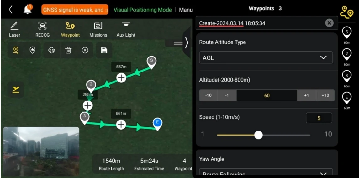
PDF p. 123In the toolbar (or Shortcuts), tap the illustrated icon to enter the "Waypoint" mission interface. You can add multiple waypoints on the map. Every two neighboring waypoints connect to form a flight segment and one or more flight segments form a route. By setting the flight altitude, flight speed, camera action, and waypoint actions of each waypoint for each route and each waypoint, the aircraft will automatically fly according to the route and perform corresponding actions at each waypoint. PDF p. 123
Original instruction with its control symbol

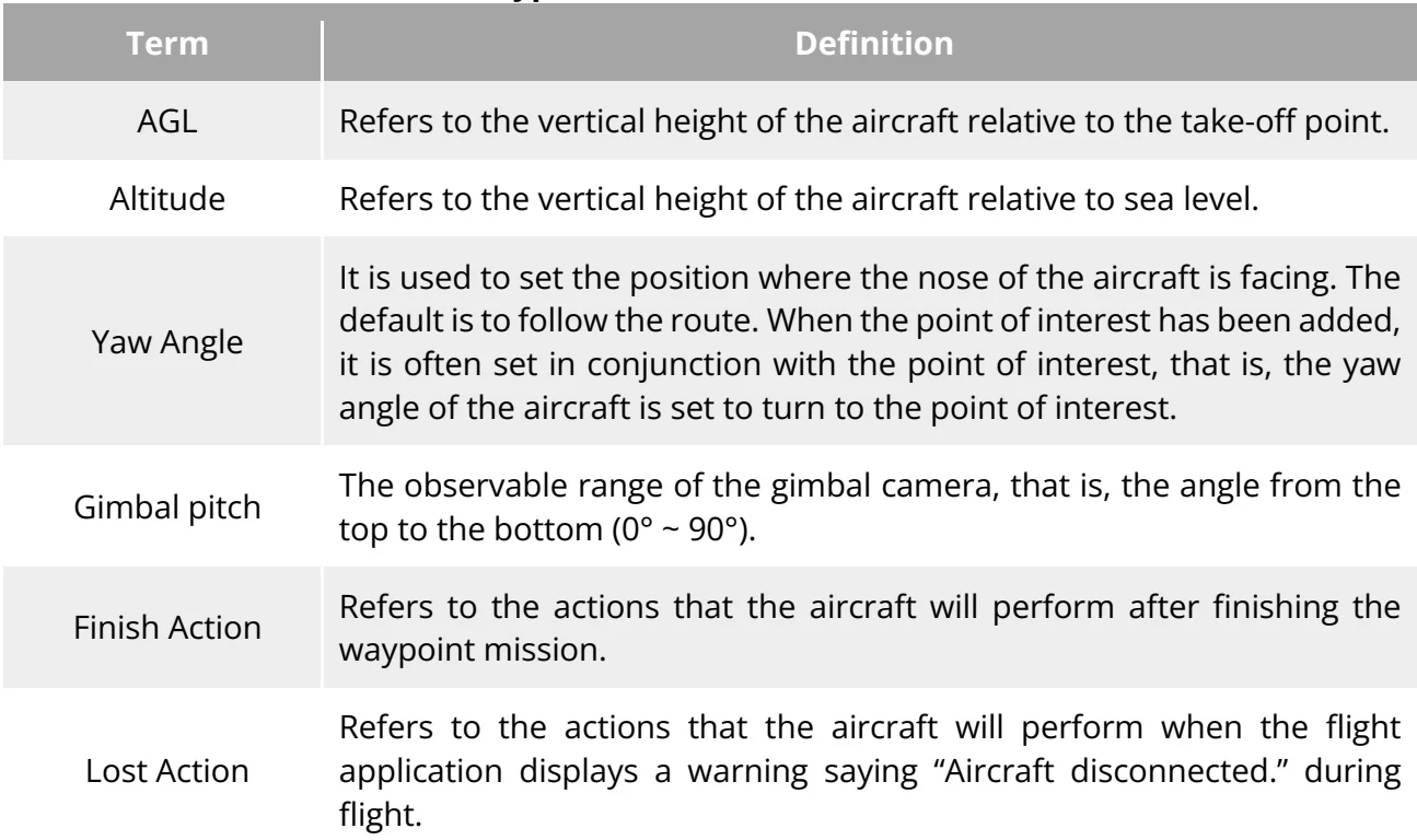
| Term | Definition |
| AGL | Refers to the vertical height of the aircraft relative to the take-off point. |
| Altitude | Refers to the vertical height of the aircraft relative to sea level. |
| Yaw Angle | It is used to set the position where the nose of the aircraft is facing. The default is to follow the route. When the point of interest has been added, it is often set in conjunction with the point of interest, that is, the yaw angle of the aircraft is set to turn to the point of interest. |
| Gimbal pitch | The observable range of the gimbal camera, that is, the angle from the top to the bottom (0° ~ 90°). |
| Finish Action | Refers to the actions that the aircraft will perform after finishing the waypoint mission. |
| Lost Action | Refers to the actions that the aircraft will perform when the flight application displays a warning saying “Aircraft disconnected.” during flight. |
View the original table / diagram
| Segment Action | Refers to the actions performed by the camera, the gimbal, and the aircraft during the flight segment formed between the current waypoint and the next waypoint. |
| Waypoint Action | Refers to the actions performed by the camera, gimbal, and aircraft at a specific waypoint. |
View the original table / diagram

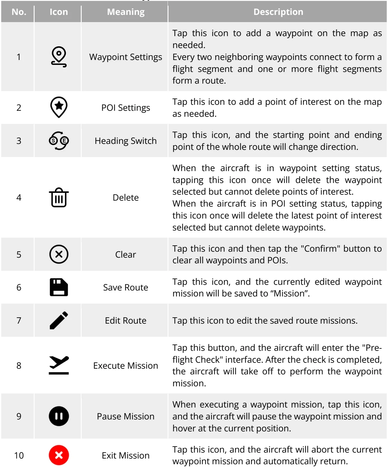
| No. | Icon | Meaning | Description |
| 1 |  | Waypoint Settings | Tap this icon to add a waypoint on the map as needed.Every two neighboring waypoints connect to form a flight segment and one or more flight segments form a route. |
| 2 |  | POI Settings | Tap this icon to add a point of interest on the map as needed. |
| 3 |  | Heading Switch | Tap this icon, and the starting point and ending point of the whole route will change direction. |
| 4 |  | Delete | When the aircraft is in waypoint setting status, tapping this icon once will delete the waypoint selected but cannot delete points of interest.When the aircraft is in POI setting status, tapping this icon once will delete the latest point of interest selected but cannot delete waypoints. |
| 5 |  | Clear | Tap this icon and then tap the "Confirm" button to clear all waypoints and POIs. |
| 6 |  | Save Route | Tap this icon, and the currently edited waypoint mission will be saved to "Mission". |
| 7 |  | Edit Route | Tap this icon to edit the saved route missions. |
| 8 |  | Execute Mission | Tap this button, and the aircraft will enter the "Pre-flight Check" interface. After the check is completed, the aircraft will take off to perform the waypoint mission. |
| 9 |  | Pause Mission | When executing a waypoint mission, tap this icon, and the aircraft will pause the waypoint mission and hover at the current position. |
| 10 |  | Exit Mission | Tap this icon, and the aircraft will abort the current waypoint mission and automatically return. |
View the original table / diagram
Add Waypoints
PDF p. 125Tap the illustrated icon, find the starting point for the mission on the map and tap it to create the first waypoint, and then repeat the previous operation to create multiple waypoints as required. PDF p. 125
Original instruction with its control symbol

When adding waypoints, the waypoint mission settings interface will pop up on the right side of the waypoint mission interface. PDF p. 125
After adding the waypoint, tap the illustrated icon in the upper-right corner of the waypoint settings interface to enter the route settings interface. PDF p. 125
Original instruction with its control symbol

Tap the waypoint icon on the right side of the waypoint settings interface to enter the corresponding waypoint settings interface. PDF p. 125
Set Route Name and Route Altitude Type
PDF p. 125On the route settings interface, tap the "Route Name" edit box and enter the name as required to set the name of a route; tap the drop-down list of "Route Altitude Type" to select “AGL” or “MSL” as the altitude type of the entire route. MSL as the altitude type of the entire route. PDF p. 125
Set Flight Altitude
PDF p. 125On the route settings interface, tap the "Flight Altitude" edit box to set the flight altitude of the whole route. PDF p. 125
On the waypoint settings interface, the flight altitude is set to “Align Route” by default. After deselecting “Align Route”, tap the "Flight Altitude" edit box to set the flight altitude for the whole route. PDF p. 125
Set Flight Speed
PDF p. 125On the route settings interface, tap the “Speed” edit box to set the flight speed value of the whole route PDF p. 125
On the waypoint settings interface, the flight speed is set to “Align Route” by default. After deselecting “Align Route”, tap the "Speed" edit box to set the flight altitude for the whole route. PDF p. 125
Tip
PDF p. 125The maximum value for the flight altitude setting will be dynamically adjusted according to the altitude limit set in the "Flight Control Parameter Setting". PDF p. 125
After take-off, the aircraft will gradually adjust its "flight altitude" and "flight speed" to the set values while flying to this waypoint. PDF p. 125
Set Yaw Angle
PDF p. 125On the route settings interface, tap the drop-down list of "Yaw Angle" to set the yaw angle of the aircraft in the entire route to “Route Following”, “Manual”, or “Custom”. PDF p. 125
On the waypoint settings interface, the yaw angle of the aircraft is set to “Align Route” by default. After deselecting “Align Route”, tap the drop-down list of "Yaw Angle" to set the yaw PDF p. 125
angle of the aircraft at the current waypoint to “Route Following”, “Manual”, “Custom”, or “Turn to Point of Interest” (the waypoint should be associated with the point of interest). PDF p. 126

Note
PDF p. 126Route Following: the nose of the aircraft will follow the direction of the waypoint change. PDF p. 126
Manual: Users use the remote controller to control the nose direction of the aircraft during the flight. PDF p. 126
Custom: the aircraft nose will be adjusted according to the set yaw angle value. PDF p. 126
Turn to Point of Interest: If it is set to “Turn to Point of Interest”, the nose of the aircraft will always face the set POI. PDF p. 126
Set Obstacle Avoidance Mode
PDF p. 126On the route settings interface, the obstacle avoidance mode can be set to "Bypass" or "Off". PDF p. 126
If "Bypass" is selected, the aircraft will automatically bypass obstacles. PDF p. 126
Warning
PDF p. 126If the obstacle avoidance mode is turned off, the obstacle avoidance system of the aircraft will not be enabled. In this case, please try to choose an open area to control the aircraft. PDF p. 126
Set Camera Action
PDF p. 126On the route settings interface, tap the drop-down list of "Camera Action" to set the camera action of the entire route to “Start Recording”, “Stop Recording”, “Shoot”, “Stop Shooting”, “Timelapse”, “Distance Lapse”, and “No Action”. PDF p. 126
On the waypoint settings interface, the segment action is set to “Align Route” by default. After deselecting “Align Route”, tap the drop-down list of "Camera Action" to set the camera action of the current flight segment to “Start Recording”, “Stop Recording”, “Shoot”, “Stop Shooting”, “Timelapse”, “Distance Lapse”, and “No Action”. PDF p. 126
Note
PDF p. 126Timelapse: Take pictures continuously and periodically based on the set "photo interval" time. PDF p. 126
Distance shooting: Take pictures continuously and periodically based on the set "photo interval". PDF p. 126
Set Gimbal Pitch Angle
PDF p. 126On the route settings interface, enter the value in the edit box to the right of "Gimbal Pitch Angle (0°-90°)" to set the gimbal pitch angle of the entire route. PDF p. 126
On the waypoint settings interface, the gimbal pitch angle (segment action) is set to “Align Route” by default. After deselecting “Align Route”, enter the value in the edit box to the right of "Gimbal Pitch Angle (0°-90°)"to set the gimbal pitch angle of the current segment. PDF p. 126

Note
PDF p. 127If the camera action “Gimbal pitch angle” is added when setting the waypoint action, the aircraft will execute the initial pitch angle first when flying to the Waypoint, and then execute the "Gimbal pitch angle" in the camera action PDF p. 127
Add a Waypoint Action
PDF p. 127On the waypoint settings interface, tap the "Add Action" button under “Waypoint Action” to set the camera action, gimbal pitch angle, and yaw angle for the current waypoint. You can add a maximum of 10 waypoint actions for one waypoint. PDF p. 127
Set Finish Action
PDF p. 127On the route settings interface, tap the drop-down list of "Finish Action" to set the flight action of the aircraft after completing the waypoint mission. PDF p. 127
If “Auto RTH” is selected, the aircraft will automatically return to the home point after completing the mission. PDF p. 127
If “Hovering” is selected, the aircraft will hover at the end point after completing the mission. PDF p. 127
Set Signal Loss Action
PDF p. 127On the route settings interface, tap the drop-down list of "Signal Loss Action" to set the flight action of the aircraft after losing connection with the remote controller. PDF p. 127
If "Continue" is selected, the aircraft will continue to execute the mission and perform the "Finish Action" after completing the mission. PDF p. 127
If “Auto RTH” is selected, the aircraft will automatically return to the home point. PDF p. 127
Set Waypoint Coordinates
PDF p. 127After adding a waypoint, you can automatically obtain the longitude and latitude parameters of the waypoint. You can also manually enter and modify the longitude and latitude of the waypoint. PDF p. 127
Under “Waypoint Coordinates” on the waypoint settings interface, the waypoint coordinates can be set in three formats: WGS84/DD, WGS84/DMS, and WGS84/MGRS. Tap the "Longitude" and "Latitude" edit boxes below and enter the longitude and latitude of the waypoint to complete the modification of the waypoint coordinates. PDF p. 127
When using the WGS84/DD (Decimal Degrees) format, you can use the arrow keys located on the right side of the editing field to make fine adjustments to the longitude and latitude. PDF p. 127
Add Point of Interest
PDF p. 127On the waypoint mission interface, tap the illustrated icon, find the specific location on the map where the POI needs to be set and tap it to create the first POI, and then repeat the previous operation to create multiple POIs as required. PDF p. 127
Original instruction with its control symbol

When adding POIs, the POI setting interface will pop up on the right side of the waypoint mission interface. PDF p. 127
Set POI Altitude
PDF p. 127In the "Altitude" edit box, set the altitude of the point of interest. PDF p. 127
Important
PDF p. 127POI Altitude is the altitude of the point of interest relative to takeoff point. PDF p. 127
When the point of interest is higher than the waypoint, the gimbal camera cannot look at the point of interest above. PDF p. 127
Set Associated Waypoints
PDF p. 128On the POI settings interface, tap the waypoints to be associated to associate the current point of interest with the selected waypoints. PDF p. 128
Tip
PDF p. 128After a waypoint is associated with a point of interest, the yaw angle of the aircraft at the waypoint will not be set to “Align Route” by default. If the “Yaw Angle” of the aircraft at the waypoint is set to “Turn to Point of Interest”, the nose of the aircraft will always face the associated point of interest during the flight segment from this waypoint to the next waypoint when the waypoint mission is executed. PDF p. 128
Start Pre-flight Check
PDF p. 128After the completion of all settings for a route, relevant flight mission data will be synchronously displayed at the bottom center of the waypoint mission interface, including the route length, estimated time, waypoints, and photos to be taken. Tap the illustrated icon on the left side to enter the "Pre-flight Check" interface. PDF p. 128
Original instruction with its control symbol

Upload a Route and Start a Mission
PDF p. 128After completing the pre-flight check, press the “Slide to takeoff” icon at the bottom of the "Pre-flight Check" interface, and the aircraft will automatically take off to execute the mission. The estimated completion time, current photo count, current altitude, current wind speed, and other basic information will be synchronously displayed at the bottom center of the waypoint mission interface. The lower-left mini screen displays the current view observed by the gimbal camera. Tap to enlarge it to full screen for viewing. PDF p. 128
When the aircraft completes the waypoint mission, the relevant flight mission data of this route will be displayed at the bottom center of the map, including the route length, estimated time, waypoint, the number of photos taken, and the number of flights. PDF p. 128
6.9.2 Rectangle/Polygon Mission
PDF p. 128In the toolbar (or shortcuts), tap the illustrated icon to enter the "Rectangle" mission interface. You can add a rectangular area on the map and perform operations such as dragging, scaling, and rotating to adjust the position and size of the area. After adjustments, the flight application will automatically generate a continuous series of equidistant flight routes within the rectangular area based on the side overlap and course angle settings. The aircraft will then automatically fly to execute the shooting mission according to these flight routes and relevant settings. PDF p. 128
Original instruction with its control symbol

In the toolbar (or shortcuts), tap the illustrated icon to enter the "Polygon" mission interface. You can add a square area on the map and perform operations such as dragging, adding side boundaries, and dragging corner points to adjust the position and size of the area. After adjustments, the flight application will automatically generate a continuous series of equidistant flight routes within the polygonal area based on the side overlap and course angle settings. The aircraft will then automatically fly to execute the shooting mission according to these flight routes and relevant settings. PDF p. 128
Original instruction with its control symbol
| Term | Definition |
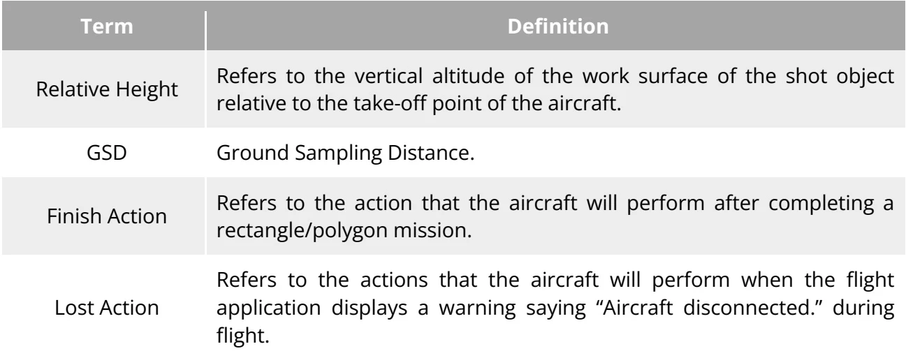
| Relative Height | Refers to the vertical altitude of the work surface of the shot object relative to the take-off point of the aircraft. |
| GSD | Ground Sampling Distance. |
| Finish Action | Refers to the action that the aircraft will perform after completing a rectangle/polygon mission. |
| Lost Action | Refers to the actions that the aircraft will perform when the flight application displays a warning saying “Aircraft disconnected.” during flight. |
View the original table / diagram
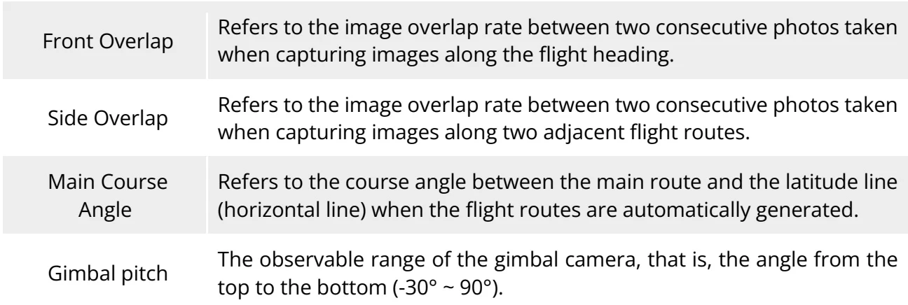
| Front Overlap | Refers to the image overlap rate between two consecutive photos taken when capturing images along the flight heading. |
| Side Overlap | Refers to the image overlap rate between two consecutive photos taken when capturing images along two adjacent flight routes. |
| Main Course | Refers to the course angle between the main route and the latitude line |
| Angle | (horizontal line)when the flight routes are automatically generated. |
| Gimbal pitch | The observable range of the gimbal camera, that is, the angle from the top to the bottom (-30° ~ 90°). |
View the original table / diagram
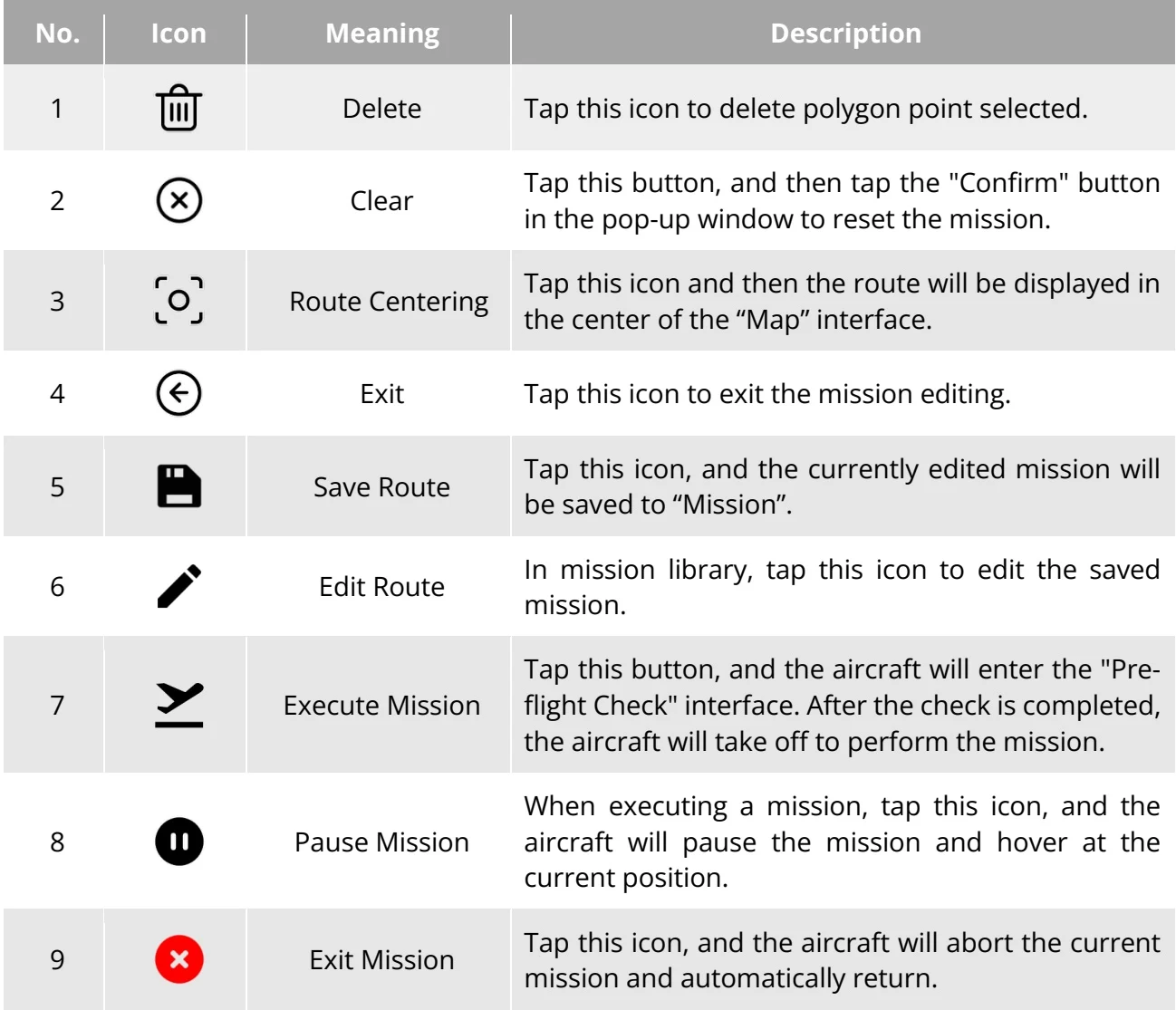
| No. | Icon | Meaning | Description |
| 1 | Delete | Tap this icon to delete polygon point selected. | |
| 2 | Clear | Tap this button, and then tap the "Confirm" button in the pop-up window to reset the mission. | |
| 3 | Route Centering | Tap this icon and then the route will be displayed in the center of the "Map" interface. | |
| 4 | Exit | Tap this icon to exit the mission editing. | |
| 5 | Save Route | Tap this icon, and the currently edited mission will be saved to "Mission". | |
| 6 | Edit Route | In mission library, tap this icon to edit the saved mission. | |
| 7 | Execute Mission | Tap this button, and the aircraft will enter the "Pre-flight Check" interface. After the check is completed, the aircraft will take off to perform the mission. | |
| 8 | Pause Mission | When executing a mission, tap this icon, and the aircraft will pause the mission and hover at the current position. | |
| 9 | Exit Mission | Tap this icon, and the aircraft will abort the current mission and automatically return. |
View the original table / diagram
Add a Rectangular/Polygonal Area
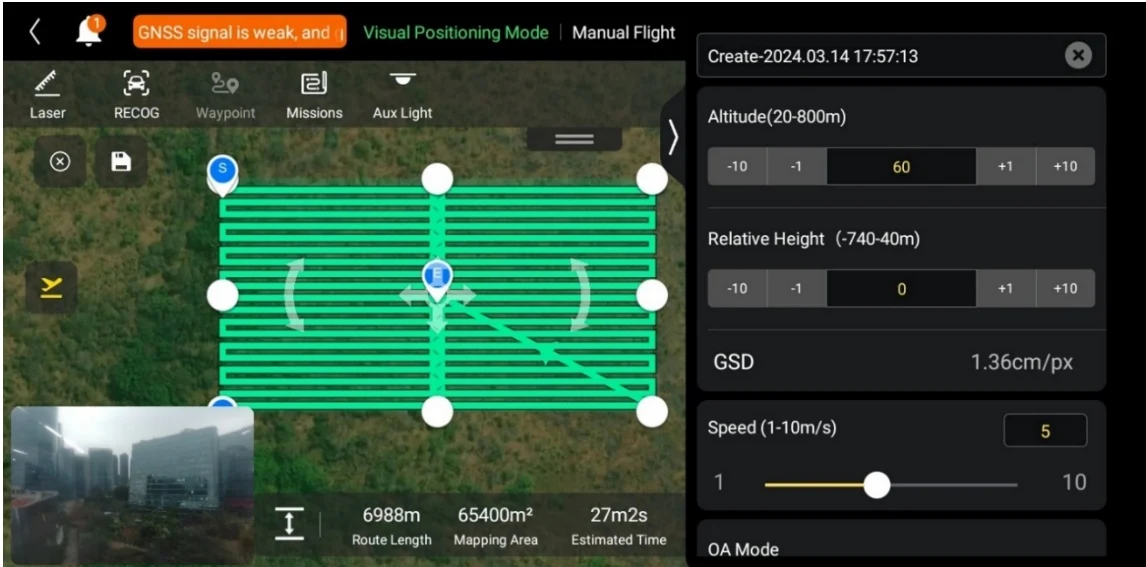
PDF p. 130On the map of the rectangle mission interface, find the center point of the mission to be executed and tap it to automatically generate a rectangular area. You can adjust the area of the rectangle by dragging the eight white points at the edges of the rectangle. You can drag the "cross arrow" in the center of the rectangle to move the rectangle or drag the "curved arrow" on both sides of the rectangle to rotate the rectangle around the center point. PDF p. 130
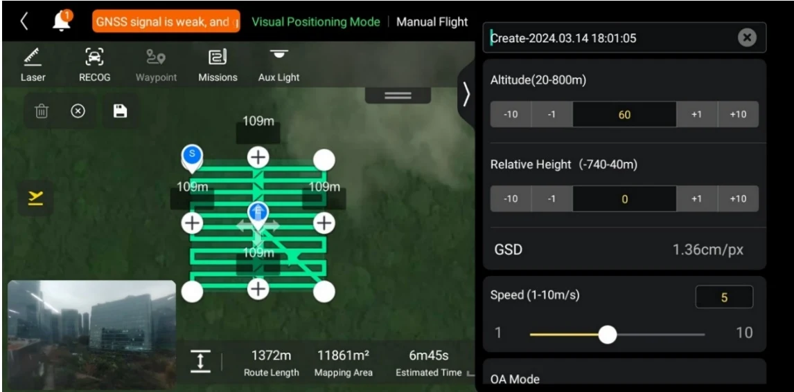
On the map of the polygon mission interface, find the center point of the mission to be executed and tap it to automatically generate a square area. You can tap the "+" icon between two white points to add side lines for the area. You can drag the white points to adjust the positions of the corner points of the polygon, which allows you to modify the area of the polygon. You can also drag the "cross arrow" in the center of the polygonal area to move the polygon. PDF p. 131
When adding a rectangular/polygonal area, the mission settings interface will pop up on the right side of the mission interface. PDF p. 131
Tip
PDF p. 131A rectangular/polygonal area includes two waypoints, that is, the starting point ( ) and the end point ( ). PDF p. 131
Set Mission Name
PDF p. 131On the rectangle/polygon mission settings interface: PDF p. 131
Tap the "Mission Name" edit box and enter the name as required to set the name of a rectangle/polygon mission. PDF p. 131
Set Flight Altitude and Relative Height
PDF p. 131Tap the "Flight Altitude (20-800m)" edit box on the mission settings interface to set the flight altitude value of the rectangle/polygon mission. PDF p. 131
The setting range of "Relative Height" will automatically be dynamically adjusted according to the flight altitude setting. In the edit box, directly enter the mission altitude value or tap the shortcut buttons on the left and right sides to adjust the value. This way, you set the relative altitude of the rectangle/polygon mission. PDF p. 131
Tip
PDF p. 131The maximum value for the flight altitude setting will be dynamically adjusted according to the altitude limit set in the "Flight Control Parameter Setting". PDF p. 131
GSD varies with different flight altitude values. PDF p. 131
Set Flight Speed
PDF p. 131Tap the "Flight Speed" edit box to set the flight speed of rectangle/polygon mission. PDF p. 131
Set Obstacle Avoidance Mode
PDF p. 131On the rectangle mission settings interface, the obstacle avoidance mode can be set to "Bypass" or "Off". PDF p. 131
If "Bypass" is selected, the aircraft will automatically bypass obstacles. PDF p. 131
Warning
PDF p. 131If the obstacle avoidance mode is turned off, the obstacle avoidance system of the aircraft will not be enabled. In this case, please try to choose an open area to control the aircraft. PDF p. 131
Tip
PDF p. 132When flying at a high altitude, if there are no obstacles, it is recommended to disable the obstacle avoidance mode. PDF p. 132
Set Finish Action
PDF p. 132On the rectangle/polygon mission settings interface, tap the drop-down list of "Finish Action" to set the flight action of the aircraft after completing the rectangle/polygon mission. PDF p. 132
If “Auto RTH” is selected, the aircraft will automatically return to the home point after completing the mission. PDF p. 132
If “Hovering” is selected, the aircraft will hover at the end point after completing the mission. PDF p. 132
Set Signal Loss Action
PDF p. 132On the rectangle/polygon mission settings interface, tap the drop-down list of "Signal Loss PDF p. 132
Action" to set the flight action of the aircraft after losing connection with the remote controller. PDF p. 132
If "Continue" is selected, the aircraft will continue to execute the mission and perform the "Finish Action" after completing the mission. PDF p. 132
If “Auto RTH” is selected, the aircraft will automatically return to the home point. PDF p. 132
Advanced Settings
PDF p. 132On the rectangle/polygon mission settings interface, tap “Advanced Settings” to enter the advanced settings interface and set the front overlap, side overlap, main course angle, and gimbal pitch angle for the rectangle mission. PDF p. 132
If “Custom” is selected, you can directly adjust the angle between the main route of the rectangle/polygon mission and the latitude line. PDF p. 132
Tip
PDF p. 132The setting range of the front overlap and side overlap is 10%-90%, and the default value is 70%. PDF p. 132
Turn On/Off Elevation Optimization
PDF p. 132If this function is turned on, the aircraft will create a route along the center point of the rectangle for re-shooting after completing the shooting of the main route. This helps optimize the overall shooting accuracy of the mission. PDF p. 132
Turn On/Off Double Grid PDF p. 132
If this function is turned on, the aircraft will change its heading by 90° and shoot the rectangle/polygon mission area again after completing the shooting of the main route. The two routes have a 90° overlap. PDF p. 132
Turn On/Off Route Extension
PDF p. 132Due to the limited gimbal pitch angle and flight altitude, some areas on the outer edges of the rectangle/polygon mission area might not be captured by the camera. In such cases, you need to turn on route extension to extend the rectangle mission area so as to ensure complete coverage of the target area. PDF p. 132
Photo Compatibility Settings
PDF p. 132Tap “EXIF Compatibility” drop-down list to set the storage compatibility standard of the aircraft shooting picture. Available format options are ‘Pix4d” and “Standard”. PDF p. 132
Start Pre-flight Check
PDF p. 133After the completion of all settings for a rectangle/polygon mission, relevant flight mission data will be synchronously displayed at the bottom center of the rectangle mission interface, including the route length, mapping area, estimated time, and photos to be taken. Tap the illustrated icon on the left side to enter the "Pre-flight Check" interface. PDF p. 133
Original instruction with its control symbol

Upload a Route and Start a Mission
PDF p. 133After completing the pre-flight check, press the “Slide to takeoff” icon at the bottom of the "Pre-flight Check" interface, and the aircraft will automatically take off to execute the mission. The estimated completion time, current photo count, current altitude, current wind speed, and other basic information will be synchronously displayed at the bottom center of the rectangle mission interface. The lower-left mini screen displays the current view observed by the gimbal camera. Tap to enlarge it to full screen for viewing. PDF p. 133
When the aircraft completes the rectangle/polygon mission, the relevant flight mission data of this route will be displayed at the bottom center of the map, including the route length, mapping area, estimated time, the number of photos taken, and the number of flights. PDF p. 133
6.9.3 Oblique
PDF p. 133In the toolbar (or More), tap the illustrated icon to enter the "Oblique" mission interface. You can add a square area on the map and perform operations such as dragging, scaling, and rotating to adjust the position and size of the area. After adjustments, the flight application will automatically generate a continuous series of equidistant flight routes within the area based on the side overlap and course angle settings. The aircraft will then automatically fly to execute the mission according to these flight routes and relevant settings. PDF p. 133
Original instruction with its control symbol

| Term | Definition |
| Relative Height | Refers to the vertical altitude of the work surface of the shot object relative to the take-off point of the aircraft. |
| GSD | Ground sample distance when executing orthophoto route. |
| Oblique GSD | Ground sample distance when executing oblique route. |
| Finish Action | Refers to the action that the aircraft will perform after completing an oblique mission. |
| Signal Lost Action | Refers to the actions that the aircraft will perform when the flight application displays a warning saying “Aircraft disconnected.” during flight. |
| Front Overlap | Refers to the image overlap rate between two consecutive photos taken when capturing images along the flight heading in orthophoto route. |
| Oblique Front Overlap | Refers to the image overlap rate between two consecutive photos taken when capturing images along the flight heading in oblique route. |
View the original table / diagram
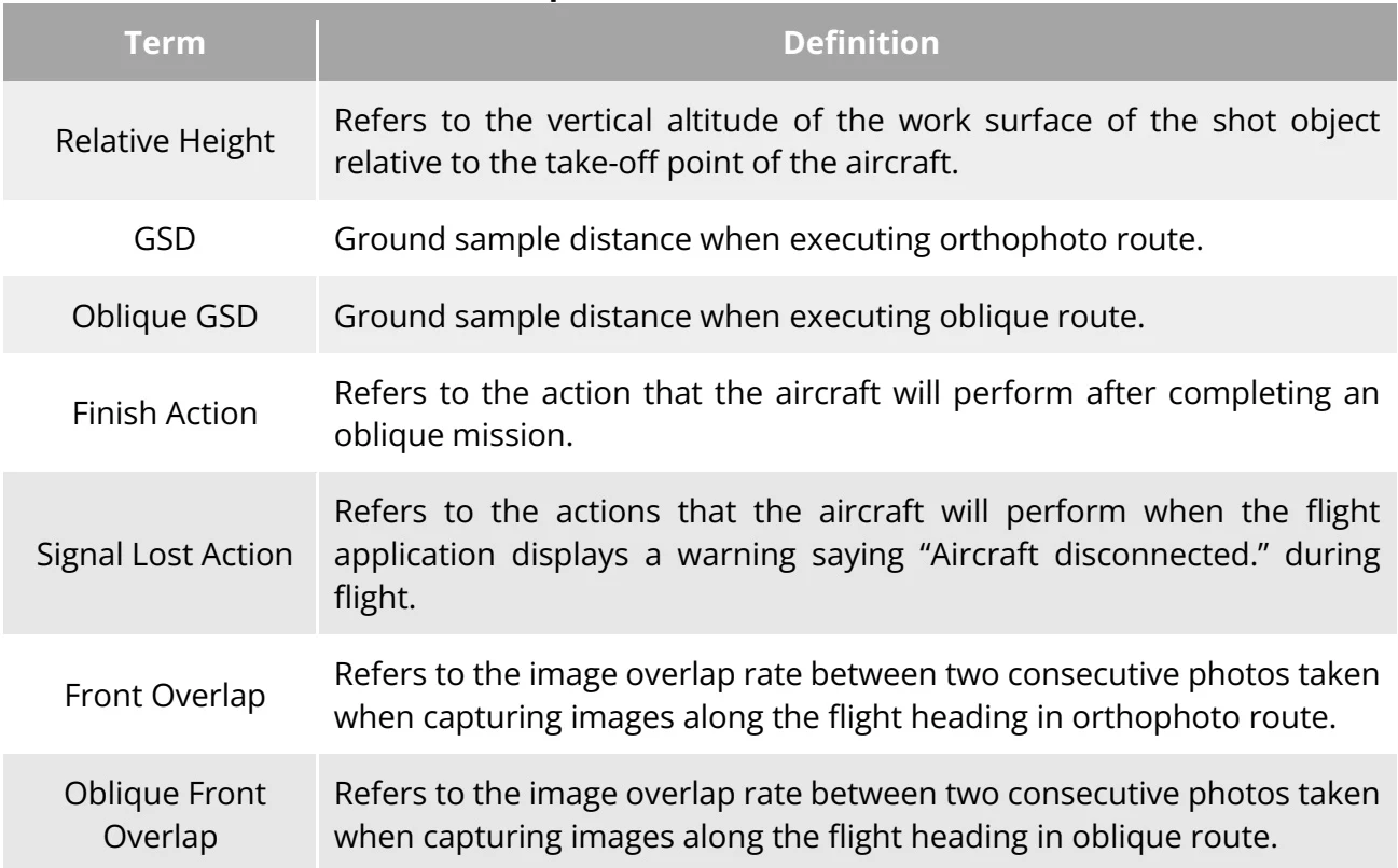
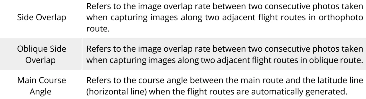
| Side Overlap | Refers to the image overlap rate between two consecutive photos taken when capturing images along two adjacent flight routes in orthophoto route. |
| Oblique Side Overlap | Refers to the image overlap rate between two consecutive photos taken when capturing images along two adjacent flight routes in oblique route. |
| Main Course Angle | Refers to the course angle between the main route and the latitude line (horizontal line) when the flight routes are automatically generated. |
View the original table / diagram
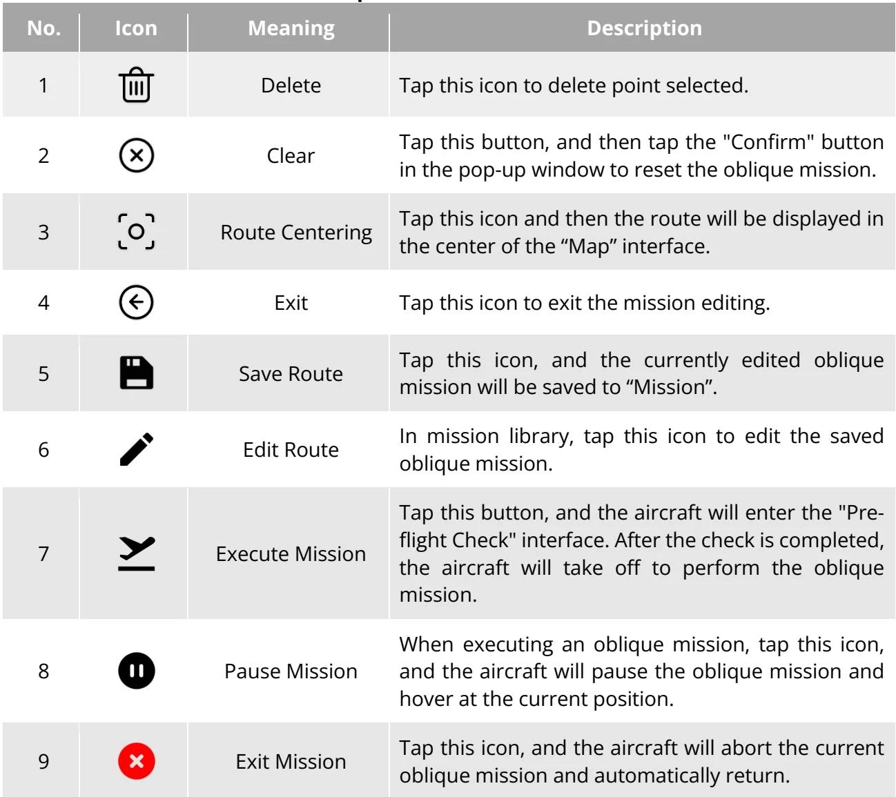
| No. | Icon | Meaning | Description |
| 1 | Delete | Tap this icon to delete point selected. | |
| 2 | Clear | Tap this button, and then tap the "Confirm" button in the pop-up window to reset the oblique mission. | |
| 3 | Route Centering | Tap this icon and then the route will be displayed in the center of the "Map" interface. | |
| 4 | Exit | Tap this icon to exit the mission editing. | |
| 5 | Save Route | Tap this icon, and the currently edited oblique mission will be saved to "Mission". | |
| 6 | Edit Route | In mission library, tap this icon to edit the saved oblique mission. | |
| 7 | Execute Mission | Tap this button, and the aircraft will enter the "Pre-flight Check" interface. After the check is completed, the aircraft will take off to perform the oblique mission. | |
| 8 | Pause Mission | When executing an oblique mission, tap this icon, and the aircraft will pause the oblique mission and hover at the current position. | |
| 9 | Exit Mission | Tap this icon, and the aircraft will abort the current oblique mission and automatically return. |
View the original table / diagram
Add Mission Area
PDF p. 135When editing the oblique mission interface, find the center point of the mission to be executed and tap it to automatically generate a square area. You can adjust the area of the square by dragging the eight white points at the edges of the square. You can drag the "cross arrow" in the center of the square to move it or drag the "curved arrow" on both sides of the square to rotate it around the center point. PDF p. 135
When adding a mission area, the mission settings interface will pop up on the right side of the mission interface. PDF p. 136
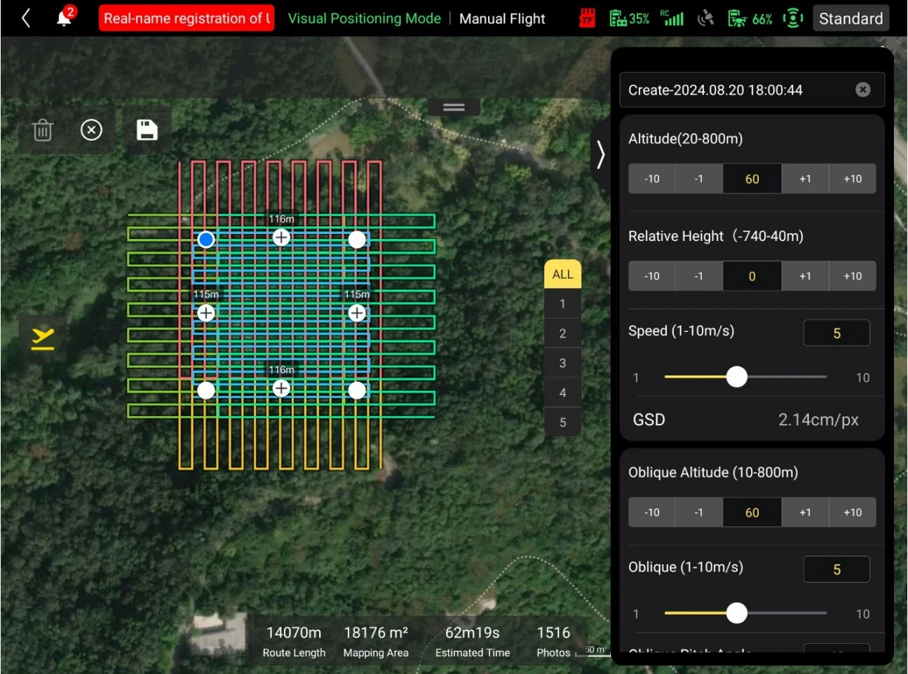
After adding a mission area, the flight application will automatically generate one set of orthophoto image routes and four sets of oblique photography routes according to the mission area. The layer number of the orthophoto image route is 1, and the layer numbers of the oblique photography routes are 2/3/4/5. When editing the mission area, selecting "ALL" can view all routes, and selecting any layer number can view the corresponding route. PDF p. 136
Tip
PDF p. 136A set of route includes two waypoints, that is, the starting point ( ) and the end point ( ). PDF p. 136
Set Mission Name
PDF p. 136Tap the "Mission Name" edit box and enter the name as required to set the name of an oblique mission. PDF p. 136
Set Flight Altitude and Relative Height
PDF p. 136Tap the "Flight Altitude (20-800m)" edit box on the mission settings interface to set the flight altitude value of the orthophoto image routes in oblique mission. PDF p. 136
The setting range of "Relative Height" will automatically be dynamically adjusted according to the flight altitude setting. In the edit box, directly enter the mission altitude value or tap the shortcut buttons on the left and right sides to adjust the value. This way, you set the relative altitude of the orthophoto image routes in oblique mission. PDF p. 136
Set Flight Speed
PDF p. 136Tap the "Flight Speed" edit box to set the flight speed of oblique mission. PDF p. 136
Tip
PDF p. 136The maximum value for the flight altitude setting will be dynamically adjusted according to the altitude limit set in the "Flight Control Parameter Setting". PDF p. 136
GSD varies with different flight altitude values. PDF p. 136
Set Oblique Altitude
PDF p. 136Tap the "Oblique Altitude" edit box to set the flight altitude of oblique photography routes in oblique mission. PDF p. 136
Set Oblique Flight Speed
PDF p. 136Tap the "Oblique Flight Speed" edit box to set the flight speed of oblique photography routes in oblique mission. PDF p. 136
Set Oblique Pitch Angle
PDF p. 136Tap the "Oblique Pitch Angle" edit box to set the gimbal pitch angle of oblique photography routes in oblique mission. PDF p. 136
Tip
PDF p. 136Oblique GSD varies with different flight altitude values. PDF p. 136
Set Weather
PDF p. 137Tap the "Weather" drop-down list to set the weather status when the aircraft is executing the oblique mission. You can choose “Sunny” or “Cloudy”. PDF p. 137
Tip
PDF p. 137Please choose the weather status according to actual weather status so as to ensure oblique photography quality. PDF p. 137
Set Finish Action
PDF p. 137On the oblique mission settings interface, tap the drop-down list of "Finish Action" to set the flight action of the aircraft after completing the oblique mission. PDF p. 137
If “Auto RTH” is selected, the aircraft will automatically return to the home point after completing the mission. PDF p. 137
If “Hovering” is selected, the aircraft will hover at the end point after completing the mission. PDF p. 137
Set Signal Loss Action
PDF p. 137On the oblique mission settings interface, tap the drop-down list of "Signal Loss Action" to set the flight action of the aircraft after losing connection with the remote controller. PDF p. 137
If "Continue" is selected, the aircraft will continue to execute the mission and perform the "Finish Action" after completing the mission. PDF p. 137
If “Auto RTH” is selected, the aircraft will automatically return to the home point. PDF p. 137
Advanced Settings
PDF p. 137On the oblique mission settings interface, tap “Advanced Settings” to enter the advanced settings interface and set the front overlap, side overlap, main course angle, and gimbal pitch angle for the oblique mission. PDF p. 137
If “Custom” is selected, you can directly adjust the angle between the main route of the oblique mission and the latitude line. PDF p. 137
Tip
PDF p. 137The setting range of the front overlap and side overlap is 10%-90%, and the default value is 70%. PDF p. 137
Set Obstacle Avoidance Mode
PDF p. 137On the oblique mission settings interface, the obstacle avoidance mode can be set to "Bypass" or "Off". PDF p. 137
If "Bypass" is selected, the aircraft will automatically bypass obstacles. PDF p. 137
Warning
PDF p. 137If the obstacle avoidance mode is turned off, the obstacle avoidance system of the aircraft will not be enabled. In this case, please try to choose an open area to control the aircraft. PDF p. 137
Start Pre-flight Check
PDF p. 138After the completion of all settings for an oblique mission, relevant flight mission data will be synchronously displayed at the bottom center of the oblique mission interface, including the route length, mapping area, estimated time, and photos to be taken. Tap the illustrated icon on the left side to enter the "Pre-flight Check" interface. PDF p. 138
Original instruction with its control symbol

Upload a Route and Start a Mission
PDF p. 138After completing the pre-flight check, press the “Slide to takeoff” icon at the bottom of the "Pre-flight Check" interface, and the aircraft will automatically take off to execute the mission. The estimated completion time, current photo count, current altitude, current wind speed, and other basic information will be synchronously displayed at the bottom center of the rectangle mission interface. The lower-left mini screen displays the current view observed by the gimbal camera. Tap to enlarge it to full screen for viewing. PDF p. 138
When the aircraft completes the oblique mission, the relevant flight mission data of this route will be displayed at the bottom center of the map, including the route length, mapping area, estimated time, the number of photos taken, and the number of flights. PDF p. 138