

In the "Settings" interface, you can set parameters such as flight control, obstacle avoidance, remote controller, image transmission, battery, and gimbal. PDF p. 105
6.5.1 Flight Control Parameter Setting
PDF p. 105In the sidebar of the “Settings” interface, tap the 叫雙 icon to enter the "Flight Control Parameter Setting" interface, where you can perform following operations, as shown below. PDF p. 105
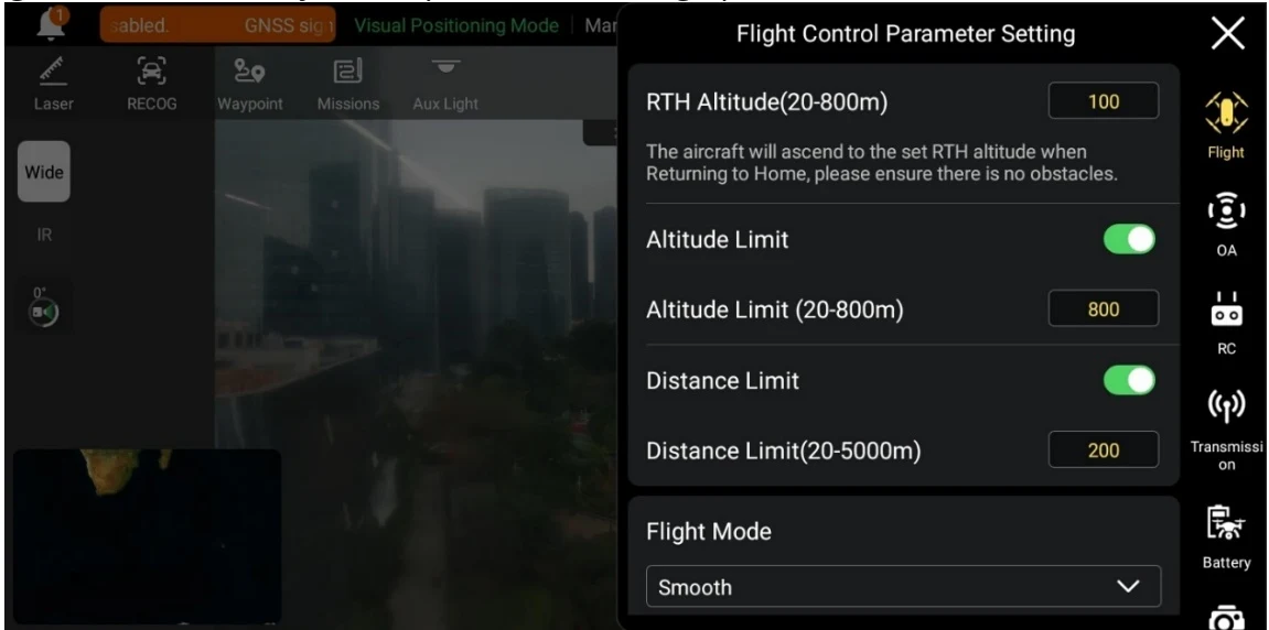
Set RTH Altitude
PDF p. 105When executing an auto-return, the aircraft will rise to the RTH altitude set before starting the return process. PDF p. 105
Warning
PDF p. 106Although the flight application allows you to set a flight altitude within the range of 20-800 meters, this does not mean that the set altitude complies with local laws and regulations. PDF p. 106
The RTH altitude should be set higher than the altitude of obstacles within the flight operation area. PDF p. 106
The RTH altitude setting should comply with local (within the flight operation area) laws and regulations. PDF p. 106
For information about adjusting the RTH altitude of the aircraft, see “2.7.4 Auto return home mechanism” in Chapter 2. PDF p. 106
Turn On/Off Altitude Limit
PDF p. 106If this function is turned on, the aircraft can rise up to the maximum altitude set. PDF p. 106
If this function is turned off, the aircraft can keep ascending according to your operation until the battery is exhausted. PDF p. 106
Turn On/Off Distance Limit
PDF p. 106If this function is turned on, the aircraft will fly within a circle with the take-off point as the center and the distance limit value set as the radius. PDF p. 106
If this function is turned off, the aircraft can keep moving according to your operation until the battery is exhausted or the signal lost action is triggered. PDF p. 106
Tip
PDF p. 106Appropriate altitude limit and distance limit settings can improve flight safety. PDF p. 106
The altitude limit setting should comply with local (within the flight operation area) laws and regulations. Flying the aircraft in an unsuitable flight altitude may have legal risks. Please comply with the fight safety requirements of relevant areas during flight operations. PDF p. 106
Set Flight Mode
PDF p. 106The aircraft supports four flight modes: Slow, Smooth, Standard, and Ludicrous. For the difference between those modes, see “3.8.2 Flight Modes” in Chapter 3. PDF p. 106
Set Home Point
PDF p. 106If "Aircraft" is selected, the home point is the position where the aircraft currently is. PDF p. 106
If "RC" is selected, the home point is the current position of the remote controller. PDF p. 106

Note
PDF p. 106If the home point is not set, the aircraft will record the take-off point as the default home point. PDF p. 106
Calibrate Compass/ IMU
PDF p. 106Perform the calibration operation as instructed in the flight application. For more information, see “2.12 Aircraft Calibration” in Chapter 2. PDF p. 106
Set Lost Action
PDF p. 107Lost action refers to the action that the aircraft will take when the aircraft is disconnected from the remote controller during flight. By default, the lost action is set to “Return to Home”. PDF p. 107
If “Return to Home” is selected, when the aircraft disconnects, the aircraft will automatically return to the home point. PDF p. 107
If "Hovering" is selected, when the aircraft disconnects, the aircraft will hover at the current position. PDF p. 107
1 7 ^ { n } \tan d is selected, when the aircraft disconnects, the aircraft will land at the current position. PDF p. 107
Tip
PDF p. 107When the aircraft initiates a return to home due to a disconnection, even if the aircraft reconnects to the remote controller, it will continue the return process. In this case, you can press the pause button \textcircled{o} \eta on the remote controller for 2 seconds until the RC emits “beep” sound to pause or exit auto return and you can pull the pitch stick to pause the return process. After exiting the auto return, the RC will regain the control of the aircraft. PDF p. 107
6.5.2 OA Settings
PDF p. 107In the sidebar of the “Settings” interface, tap the m \widehat { \underline { { \underline { { \mathbf { \varepsilon } } } } } } 1 ^ { m } icon to enter the "OA Settings" interface, where you can perform following operations, as shown below. PDF p. 107
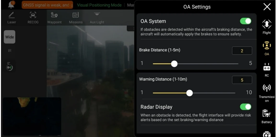
Turn On/Off OA System
PDF p. 107If this function is turned on, you can set the brake distance. When the aircraft detects an obstacle, it will brake and stop at the brake distance as set. PDF p. 107
If this function is turned off, when the aircraft detects an obstacle, it will not stop and brake. PDF p. 107
Warning
PDF p. 108To ensure flight safety, it is recommended to always turn the OA system on. PDF p. 108
When the flight mode of the aircraft is set to “Ludicrous”, the OA system function is unavailable. PDF p. 108
Set Warning Distance
PDF p. 108If the aircraft detects an obstacle, it will send a warning at the “Warning Distance” as set. PDF p. 108
Turn On/Off Radar Display
PDF p. 108If this function is turned on, when the aircraft detects an obstacle, it will provide risk warnings on the camera interface based on the set brake/warning distance. PDF p. 108
If this function is turned off, when the aircraft detects an obstacle, it will not provide risk warnings on the camera interface. PDF p. 108
Turn On/Off Obstacle Detection Notification Sound PDF p. 108
If this function is turned on, when the aircraft detects an obstacle, it will emit an audible alert. PDF p. 108
Turn On/Off Landing Protection PDF p. 108
If this function is turned on, the aircraft will detect whether the ground surfaces are suitable for landing before it lands. PDF p. 108
Tip
PDF p. 108After the landing protection function is turned on, if the aircraft detects that the ground surface is not suitable for landing, it will keep hovering over the landing point. In this case, you need to use the command sticks to manually control the aircraft to land at an appropriate location. PDF p. 108
6.5.3 RC Settings
PDF p. 108In the sidebar of the “Settings” interface, tap the \frac{1}{122} icon to enter the "RC Settings" interface, where you can perform following operations, as shown below. PDF p. 108
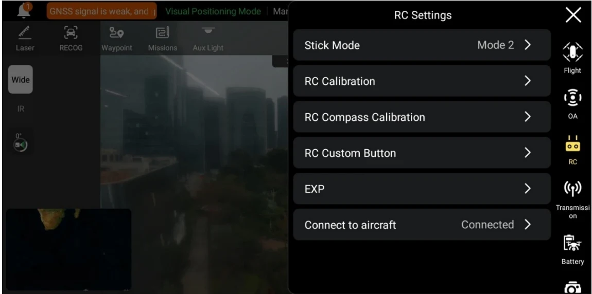
Set Stick Mode
PDF p. 109The aircraft supports three stick modes setting: Mode 1, Mode 2, and Mode 3. For the differences between the three stick modes, see "4.10.1 Stick Modes" in Chapter 4. The default stick mode is Mode 2. PDF p. 109
Calibrate the Remote Controller
PDF p. 109For details about calibration process, see “4.14 Calibrating the Remote Controller” in Chapter 4. PDF p. 109
Calibrate the RC Compass
PDF p. 109For details about calibration process, see “4.13 Calibrating the Remote Controller Compass” in Chapter 4. PDF p. 109
Set RC Custom Button
PDF p. 109For details about functions of RC custom button C, see “4.11.1 Custom Button C” in Chapter 4. PDF p. 109
Set EXP
PDF p. 109The X-axis is the physical output of the command stick, and the Y-axis is the logical output of the command stick. That is, the X-axis represents the movement generated by the current command stick move, and the Y-axis represents the actual response strength of the current aircraft. PDF p. 109
Connect to Aircraft
PDF p. 109Connect to aircraft: If the remote controller is currently not connected to the aircraft, tap "Connect to aircraft", and then double-click the power button of the aircraft according to the pop-up notification to complete the frequency matching between the remote controller and the aircraft. For more information, see “4.9 Frequency Matching With the Remote Controller” in Chapter 4. PDF p. 109
Cancel: If the remote controller is currently connected to the aircraft, tap "Connect to aircraft", and then tap “Cancel” in the pop-up window to disconnect the remote controller from the aircraft. PDF p. 109
6.5.4 Image Transmission Settings
PDF p. 109In the sidebar of the “Settings” interface, tap the illustrated icon to enter the "Image Transmission Settings" interface, where you can set the image transmission mode, and transmission frequency band as shown below. PDF p. 109
Original instruction with its control symbol

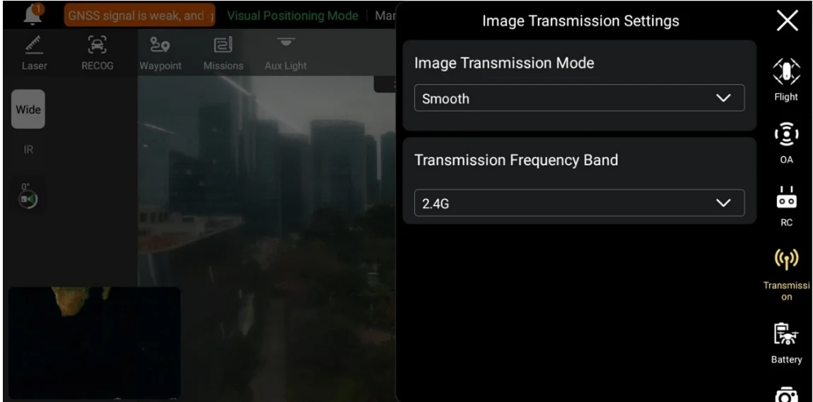
Set Image Transmission Mode
PDF p. 110The remote controller will receive and display the image transmission screen at the selected resolution. PDF p. 110
Set Transmission Frequency Band
PDF p. 110Tap the drop-down list of "Transmission Frequency Band" and select a transmission frequency band according to your needs. PDF p. 110
Auto: The optimal transmission frequency band is automatically selected for image transmission between the aircraft and the remote controller. PDF p. 110
2.4G: The 2.4 GHz frequency band is used for image transmission between the aircraft and the remote controller. PDF p. 110
5.8G: The 5.8 GHz frequency band is used for image transmission between the aircraft and the remote controller. PDF p. 110
Tip
PDF p. 110Image Transmission Mode: “Smooth” means 720P and "HD" means 1080P. PDF p. 110
The flight application will, based on the aircraft’s GNSS positioning information, automatically provide frequency band selection that comply with local laws and regulations. PDF p. 110
If the aircraft does not obtain GNSS positioning after being turned on, the image transmission frequency band between the aircraft and the RC will be set as “2.4G”. PDF p. 110
6.5.5 Aircraft Battery
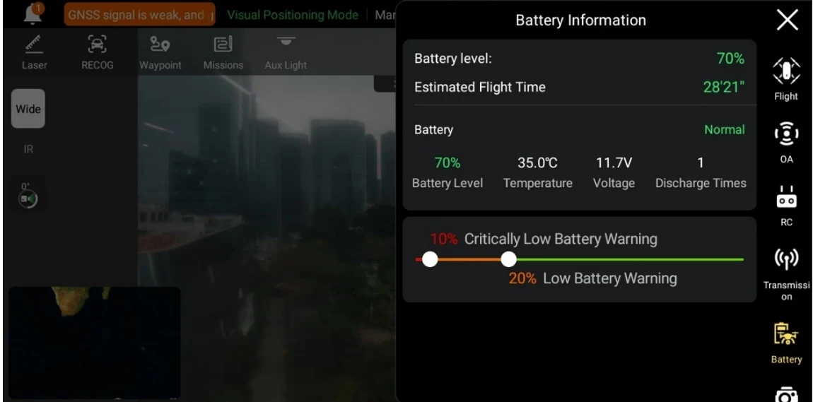
PDF p. 110In the sidebar of the “Settings” interface, tap the illustrated icon to enter the "Battery Information" interface, where you can perform following operations as shown below. PDF p. 110
Original instruction with its control symbol

View Basic Information of the Smart Battery
PDF p. 110You can view the real-time status of the battery and the estimated flight time of the aircraft with the current battery level. Please refer to the parameters in the following table to view the basic information of the battery, so as to deal with it in time when the battery condition is not good. PDF p. 110
Set Battery Warning Threshold
PDF p. 111Move the slider left or right to set warning thresholds for low battery and critically low battery. PDF p. 111
Critically Low Battery Warning: Red status. The adjustable range is from 8% to 25%. When the battery decreases to this threshold, landing is triggered forcibly. PDF p. 111
Low Battery Warning: Orange status. The adjustable range is from 15% to 50%. The low battery warning threshold should be at least 5% higher than the critically low battery warning threshold. When the battery decreases to this threshold, auto return is triggered automatically. PDF p. 111
6.5.6 Gimbal Settings
PDF p. 111In the sidebar of the “Settings” interface, tap the illustrated icon to enter the "Gimbal Settings" interface, where you can perform following operations as shown below. PDF p. 111
Original instruction with its control symbol

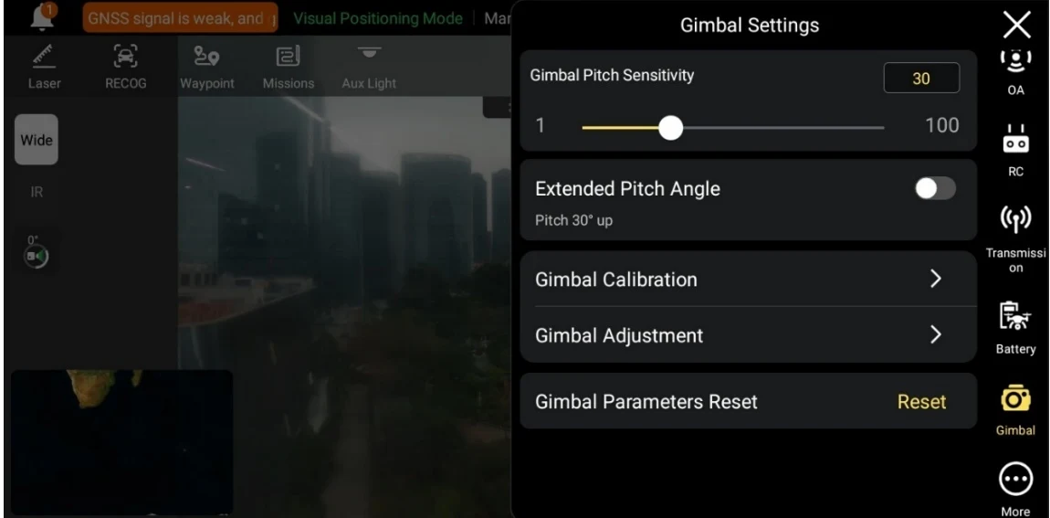
Set Gimbal Pitch Sensitivity
PDF p. 111Set the number of degrees the gimbal rotates on the pitch axis per second (unit: °/second). PDF p. 111
Turn On/Off Extended Pitch Angle
PDF p. 111Tap the button to the right of "Extended Pitch Angle" to turn on the upward gimbal rotation function. PDF p. 111
If this function is turned on, the gimbal can rotate up to 30 degrees above the level baseline. PDF p. 111
If this function is turned off, the gimbal can only maintain a level or downward rotation and cannot rotate upwards to switch to a pitch view. PDF p. 111
Gimbal Calibration
PDF p. 111For more information about gimbal calibration, see “2.12.3 Gimbal auto calibration” in Chapter 2. PDF p. 111
Gimbal Adjustment
PDF p. 111When the position of the gimbal tilts, tap “Gimbal Adjustment” and tap the buttons under the functions of “Roll”, “Yaw”, and “Pitch” to adjust the gimbal, so that the horizontal and vertical axes on the screen remain aligned to the reference objects on the three-screen image transmission screen. PDF p. 111
Gimbal Parameters Reset
PDF p. 112Reset the gimbal parameters. PDF p. 112
6.5.7 More
PDF p. 112In the sidebar of the “Settings” interface, tap the \overline { { u ( \underline { { \cdots } } ) } } _ { n } icon to enter the "More" interface, where you can perform following operations as shown below. PDF p. 112
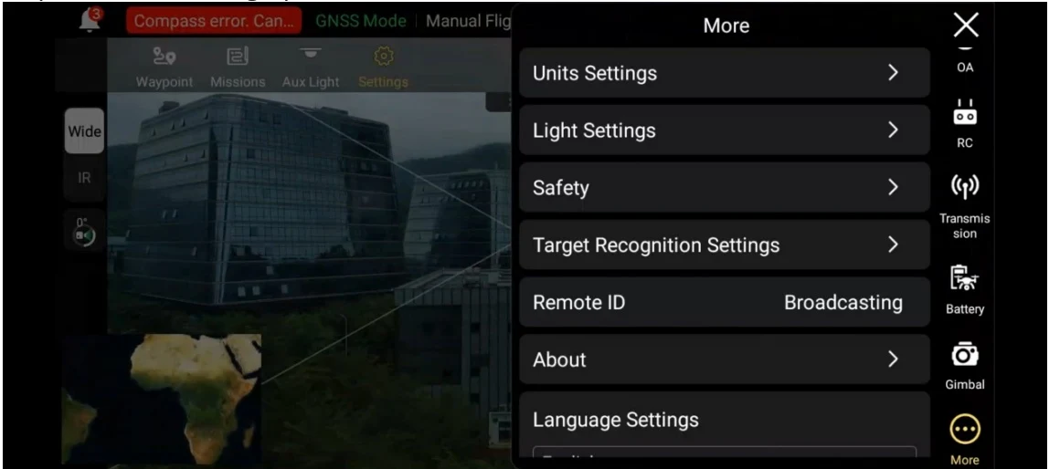
Unit Settings
PDF p. 112Set the unit of "Speed/Distance Units", "Area Units", "Temperature Units", and "Coordinate Format" displayed in the flight application. PDF p. 112
Light Settings
PDF p. 112Turn on/off Stealth mode PDF p. 112
If the stealth mode is turned on, the aux light is off by default. PDF p. 112
If the stealth mode is not turned on, you may set the aux light. PDF p. 112
Set Aux Light PDF p. 112
If \mathsf { { } ^ { n } A u t o ^ { \prime \prime } } is selected, the auxiliary bottom light is automatically turned on or off according to ambient brightness. PDF p. 112
1 1 ^ { n } \mathrm { O n } ^ { n } is selected, the auxiliary bottom light is always on by default. PDF p. 112
1 1 0 1 1 is selected, the auxiliary bottom light is off by default. PDF p. 112
Tip
PDF p. 112The auxiliary bottom light is mainly used to enhance the ambient brightness of the landing point during the landing of the aircraft, improve the sensing performance of the downward visual sensing system, and ensure landing safety. It is recommended to set it as " \mathsf { A u t o } \textbackslash mode when using the light. PDF p. 112
Turn On/Off Visual Positioning
PDF p. 112If the visual positioning function is turned on, the aircraft will hover in a place with a poor GNSS signal. PDF p. 112
Tip
PDF p. 113Turning on visual positioning is a must to enter visual positioning mode. For more information, see “3.8.1 Flight Status” in Chapter 3. PDF p. 113
Warning
PDF p. 113Before an aircraft takes off, if the visual positioning of the aircraft is turned off, do not turn on the visual positioning function after the aircraft takes off as it might lead to visual positioning failure. If you need to turn on the visual positioning function again, it is recommended to land the aircraft before conducting relevant operations. PDF p. 113
When GNSS positioning fails, if the environment lighting condition and surface texture meet the requirements, the aircraft will enter the visual positioning mode. PDF p. 113
When GNSS is unavailable, if the environment lighting condition and surface texture do not meet the requirements, the aircraft will enter the attitude mode. In this mode, operating the aircraft has high risk potential, easily leading to flight accident. PDF p. 113
Turn On/Off Submit Flight Data to CAAC
PDF p. 113According to Chinese laws and regulations, for flights conducted in China, flight data must be submitted in real time to the official system of the Civil Aviation Administration of China (CAAC) via the internet. PDF p. 113
0 Important
PDF p. 113When the network is poor, the relevant flight data will be cached on your local device, and the flight application will not store or forward the data to other services. PDF p. 113
Enter Registration No.
PDF p. 113According to Chinese laws and regulations, real-name registration is required for aircraft. For more information, see “2.1 Legal Use Notice” in Chapter 2. PDF p. 113
Emergency Stop Propellers During Flight
PDF p. 113If "Off" is selected, the "Emergency Stop Propellers During Flight" function will be disabled. PDF p. 113
If "On" is selected, you can stop the propellers of the aircraft from spinning at any time during flight by simultaneously pushing the two command sticks inward or outward. PDF p. 113
Important
PDF p. 113Please use the "Emergency Stop Propellers During Flight" function with caution. Once the propellers stop, the aircraft will fall freely without control. This function is only used to reduce additional harm or damage caused by aircraft malfunctions. Please stay away from crowds or buildings when using this function. PDF p. 113
After the "Emergency Stop Propellers During Flight" function is enabled, please stop using the aircraft and contact Autel Robotics to inspect the power system of the aircraft. PDF p. 113
Target Recognition Settings
PDF p. 114The aircraft supports three types of target for recognition: “Human”, “Vehicle” and “Boat”. Users can set a type or types of recognition on their own. PDF p. 114
Remote ID
PDF p. 114According to local laws and regulations (not Chinese Mainland), enter the pilot registration number. For more information, see “2.1 Legal Use Notice” in Chapter 2. After successful entering, broadcast status of Remote ID will be prompted. PDF p. 114
About
PDF p. 114You can view the firmware version and the serial number of the aircraft, the remote controller, the gimbal, and the battery, and check for versions and perform updates for flight application and firmware. PDF p. 114
Language Settings
PDF p. 114After you confirm the selection of a language, the flight application will automatically restart and display in the chosen language. PDF p. 114