Autel Smart Controller SE V2 is installed with the flight application Autel Enterprise by default, allowing you to operate and set the aircraft and the gimbal camera and transmit high-definition videos from the gimbal camera in real time. It offers a maximum communication distance of 12 kilometers. PDF p. 65
Remarks
PDF p. 65The maximum communication distance of the Autel Smart Controller SE V2 is measured under unblocked and interference-free conditions and is for references only. PDF p. 65
It supports adaptive frequency hopping transmission, selects the optimal channel according to the electromagnetic interference situation, and has strong anti-interference ability. PDF p. 65
The whole link data transmission between the aircraft and the remote controller adopts the AES-128 encryption method and the data storage adopts the AES-256 encryption method to ensure end-to-end data communication security. PDF p. 65
Before first use, please activate the RC’s battery by charging. PDF p. 65
4.1.1 Remote Controller Components
PDF p. 65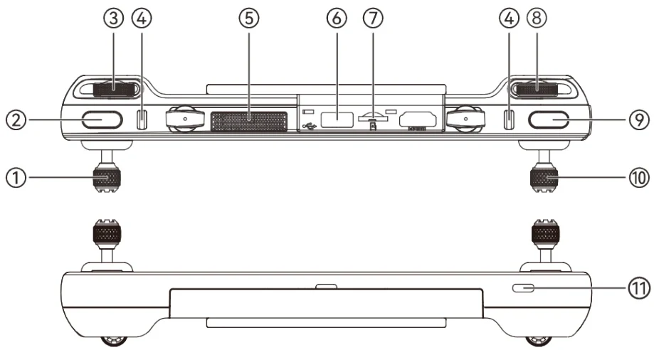
| No. | Name | Description |
| 1 | Left Command Stick | Controls the state of motion of the aircraft. The default stick mode is Mode 2. In this mode, you can use the stick to control the ascent, descent, and heading of the aircraft. You can set |
View the original table / diagram

| the stick mode in the flight application. For more information, please refer to "6.5.3 RC Settings" in Chapter 6. | ||
| 2 | C Button | Use the flight application to customize the key function. For more information, please refer to "6.5.3 RC Settings" in Chapter 6. |
| 3 | Left Dial Wheel | Turn the dial wheel to adjust the gimbal pitch. |
| 4 | Hook | Used to connect and fix the remote controller lanyard. |
| 5 | Air Outlet | For heat dissipation of the remote controller. When using it, please pay attention to whether there are foreign objects blocking the air outlet. |
| 6 | USB-A Interface | Connects to an expandable 4G/5G module or external USB device for data transmission. |
| 7 | Micro SD card slot | Used for storage expansion. |
| 8 | Right Dial Wheel | Turn the dial wheel to adjust the zoom factor of the camera. |
| 9 | Shotting/Video Recording Button | Press it to take photos; press and hold it to start recording/end recording; when recording, you may short press the button to take photo. |
| 10 | Right Stick | Controls the state of motion of the aircraft. The default stick mode is Mode 2. In this mode, you can use the stick to control the translation of the aircraft in four directions: front/back/left/right. You can set the stick mode in the flight application. For more information, please refer to "6.5.3 RC Settings" in Chapter 6. |
| 11 | USB-C Interface | Used for remote controller charging or device debugging. |
View the original table / diagram
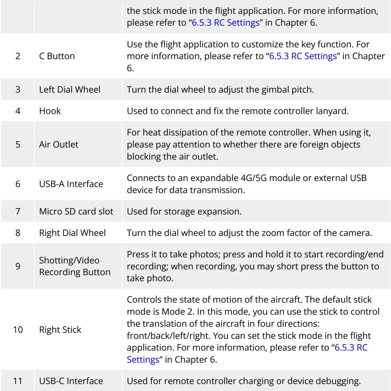
| No. | Name | Description |
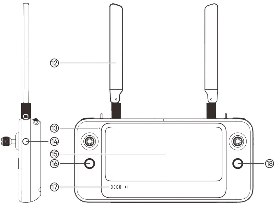
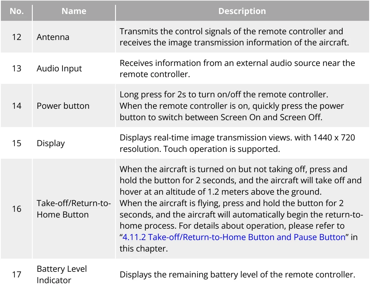
| 12 | Antenna | Transmits the control signals of the remote controller and receives the image transmission information of the aircraft. |
| 13 | Audio Input | Receives information from an external audio source near the remote controller. |
| 14 | Power button | Long press for 2s to turn on/off the remote controller.When the remote controller is on, quickly press the power button to switch between Screen On and Screen Off. |
| 15 | Display | Displays real-time image transmission views. with 1440 x 720 resolution. Touch operation is supported. |
| 16 | Take-off/Return-to-Home Button | When the aircraft is turned on but not taking off, press and hold the button for 2 seconds, and the aircraft will take off and hover at an altitude of 1.2 meters above the ground.When the aircraft is flying, press and hold the button for 2 seconds, and the aircraft will automatically begin the return-to-home process. For details about operation, please refer to "4.11.2 Take-off/Return-to-Home Button and Pause Button" in this chapter. |
| 17 | Battery Level Indicator | Displays the remaining battery level of the remote controller. |
View the original table / diagram
| 18 | Pause Button | When the aircraft is in autonomous flight mode, short press this button to control the aircraft to suspend autonomous flight and hover in place or resume autonomous flight; press and hold this button for 2 seconds to exit the autonomous flight. |
View the original table / diagram

| No. | Name | Description |
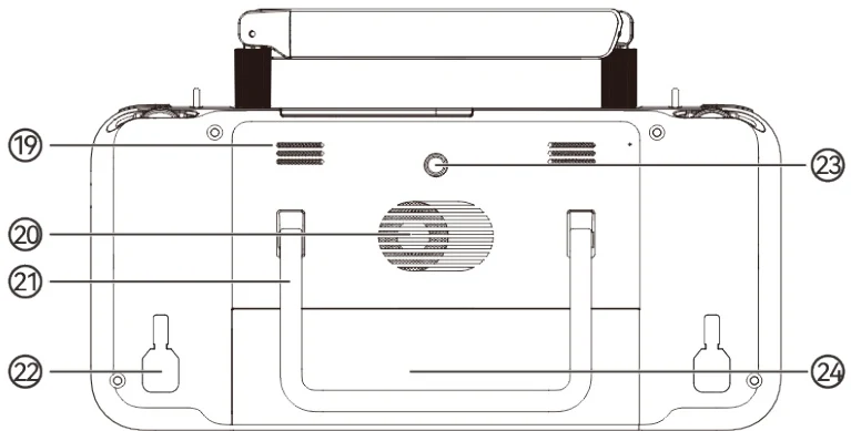
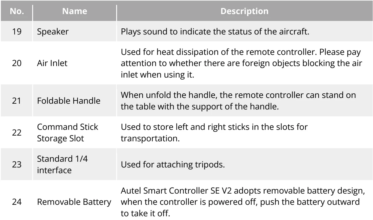
| 19 | Speaker | Plays sound to indicate the status of the aircraft. |
| 20 | Air Inlet | Used for heat dissipation of the remote controller. Please pay attention to whether there are foreign objects blocking the air inlet when using it. |
| 21 | Foldable Handle | When unfold the handle, the remote controller can stand on the table with the support of the handle. |
| 22 | Command Stick Storage Slot | Used to store left and right sticks in the slots for transportation. |
| 23 | Standard 1/4 interface | Used for attaching tripods. |
| 24 | Removable Battery | Autel Smart Controller SE V2 adopts removable battery design, when the controller is powered off, push the battery outward to take it off. |
View the original table / diagram
4.1.2 Communication Frequency Bands
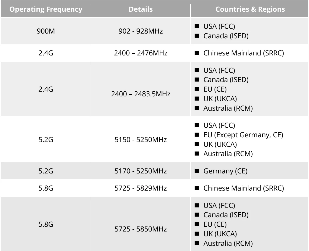
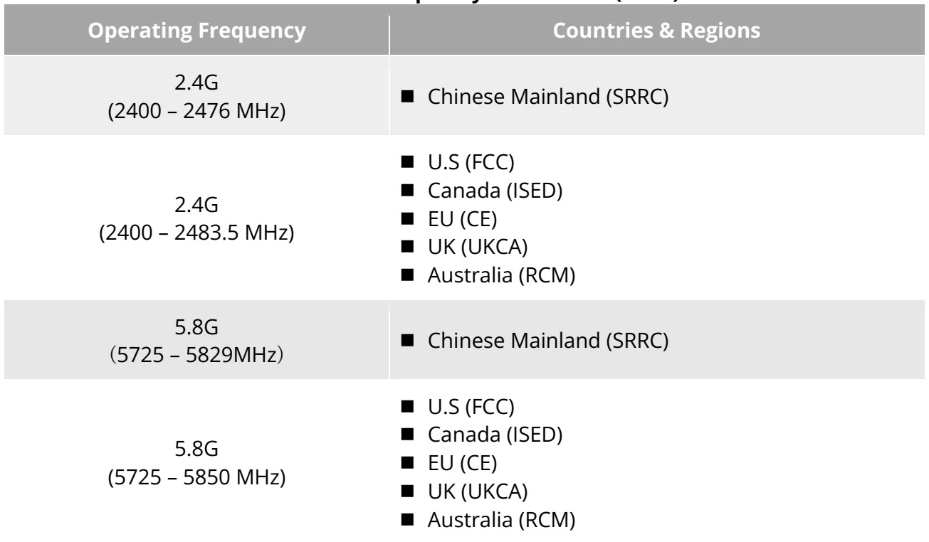
PDF p. 68The image transmission frequency bands of Autel Smart Controller SE V2 comply with regulatory requirements worldwide. Please refer to the table below for the relevant used frequency bands. PDF p. 68
After the aircraft is paired with the remote controller, the frequency bands between them will be automatically controlled by the flight application based on the geographical information of the aircraft. This is to ensure compliance with local regulations regarding frequency bands. PDF p. 69
Before flight, please ensure that the aircraft receives a strong GNSS signal after powering on. This allows the flight application to receive the proper communication frequency band. PDF p. 69
When users adopt visual positioning mode (such as in scenarios without GNSS signals), the wireless communication frequency band between the aircraft and remote controller will default to the band used in the previous flight. In this case, it is advisable to power on the aircraft in an area with a strong GNSS signal, then start flight in the actual operational area. PDF p. 69
| Operating Frequency | Details | Countries & Regions |
| 900M | 902 -928MHz | USA (FCC) Canada(ISED) |
| 2.4G | 2400 -2476MHz | Chinese Mainland(SRRC) |
| 2.4G | 2400 -2483.5MHz | USA (FCC) Canada (ISED) EU (CE) UK (UKCA) Australia (RCM) |
| 5.2G | 5150-5250MHz | USA (FCC) EU (Except Germany, CE) UK (UKCA) Australia (RCM) |
| 5.2G | 5170-5250MHz | Germany (CE) |
| 5.8G | 5725 -5829MHz | Chinese Mainland(SRRC) |
| 5.8G | 5725 -5850MHz | USA (FCC) Canada (ISED) EU (CE) UK (UKCA) Australia (RCM) |
View the original table / diagram